Basler Electric DECS-400 User Manual
Page 121
9369700990 Rev R
109
32767
10
×
=
tage
ControlVol
alue
ThresholdV
For example, to trigger a data log when the DECS-400 control voltage increases above 7 Vdc, an upper
threshold value of 22,937 would be entered:
32767
10
7
9
.
22936
×
=
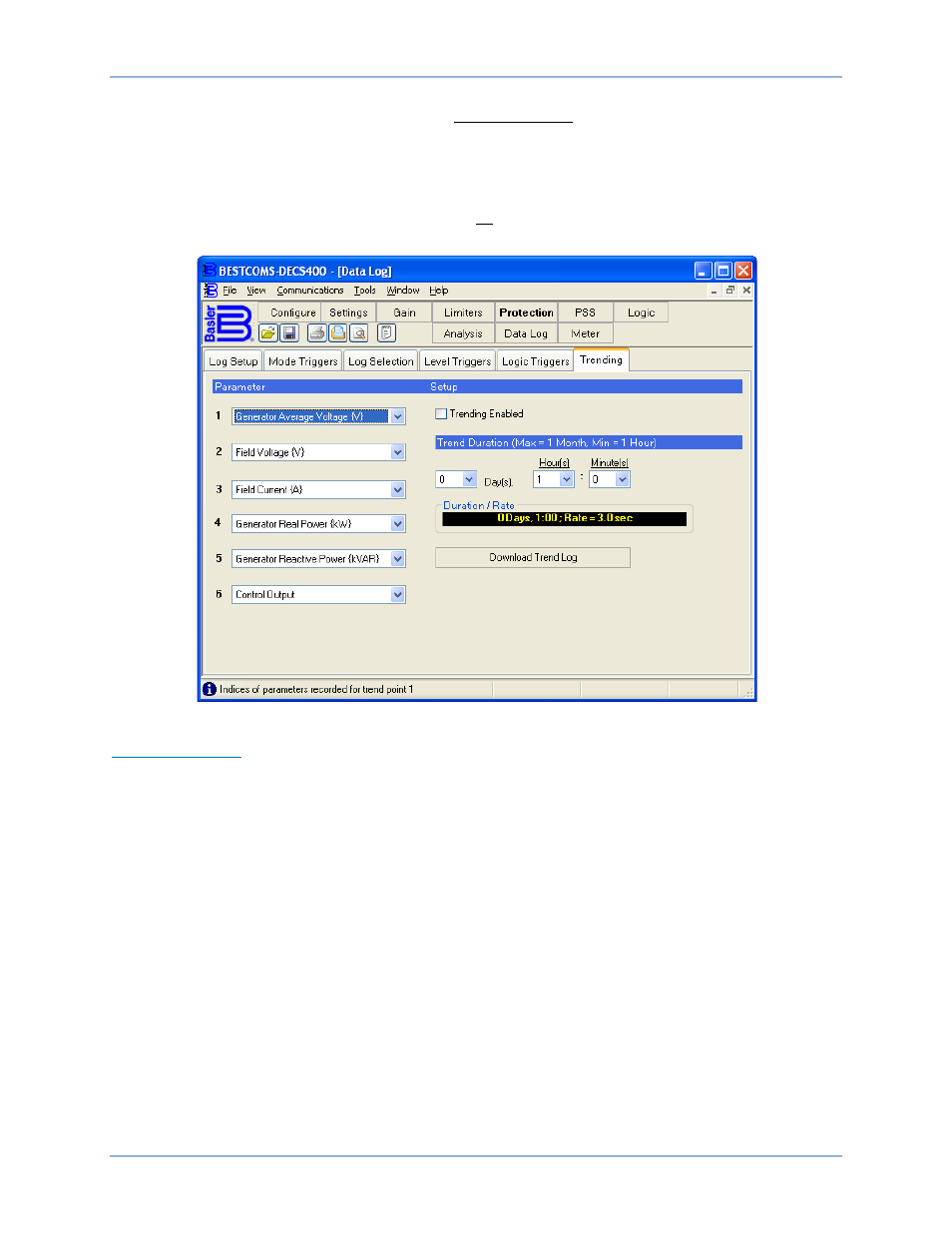
Figure 75. Data Log Screen, Level Triggers/Log Selection Tab
Logic Triggers Tab
Logic Trigger tab settings are shown in Figure 76 and described in the following paragraphs.
Alarm States. This area of the Logic Triggers tab lists the available alarm conditions that can be selected
to trigger a data log report. Any combination of alarm states may be selected.
Relay Outputs. This area of the Logic Triggers tab lists the available DECS-400 contact outputs that can
be selected to trigger a data log report. Any combination of relay outputs may be selected.
Contact Inputs. This area of the Logic Triggers tab lists the available DECS-400 contact inputs that can
be selected to trigger a data log report. Any combination of contact inputs may be selected.
DECS-400
BESTCOMS™ Software