Decs-400 programmable logic – Basler Electric DECS-400 User Manual
Page 191
9369700990 Rev R
179
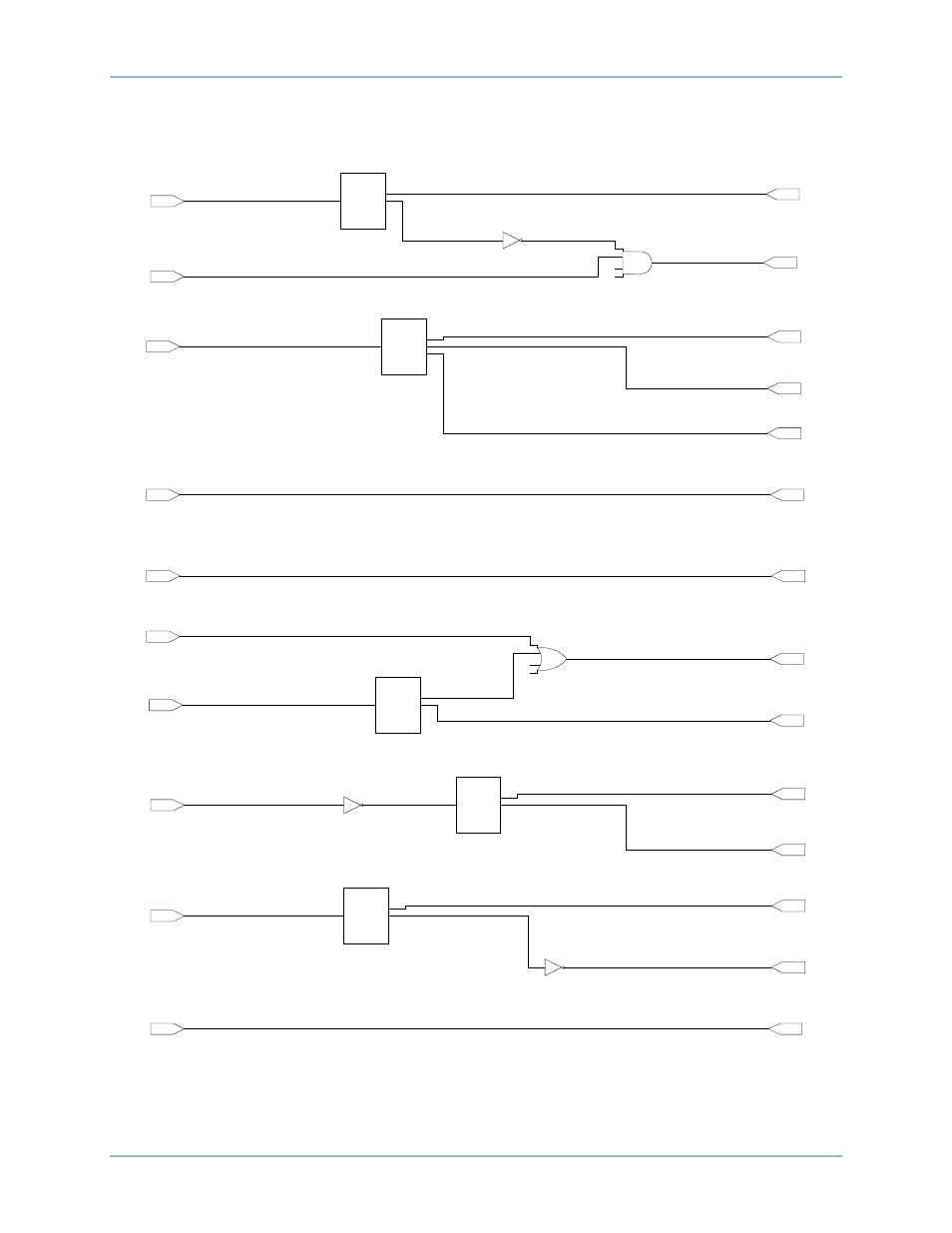
Figure 114. Dual DECS-400 With PSS (Part 2 of 3)
Switch Input 10
Disable Remote
Communication
(Input Buffer)
RS-485 Communication
Enable
(Output Buffer)
u
2
u
3
u
4
u
1
x
1
MUX
u
4
u
4
Load Compensation
Status
0=Offline; 1=Online
(Input Buffer)
OEL Option
0=Offline; 1=Online
(Output Buffer)
Voltage Matching
0=Disabled; 1=Enabled
(Output Buffer)
Layer 1
Gate 03
Switch Input 8
Secondary PSS
Settings Select
(Input Buffer)
Secondary PSS
Settings Enable
(Output Buffer)
Switch Input 6
Secondary Protection
Setttings Select
(Input Buffer)
Secondary Protectiion
Settings Enable
(Output Buffer)
Layer 1
Gate 02
u
2
u
3
u
4
u
1
x
1
MUX
u
4
u
4
Modem Access
Enable
(Output Buffer)
FCR Mode
Active
(Input Buffer)
Output Relay #1
FCR Mode Active
(Output Buffer)
PSS Mode
Active
(Input Buffer)
Secondary PID
Settings Enable
(Output Buffer)
Layer 2
Gate 02
Layer 1
Gate 01
u
2
u
3
u
4
u
1
x
1
MUX
u
4
u
4
Layer 2
Gate 04
Output Relay #6
PSS On
(Output Buffer)
P0036-12
Switch Input 5
Secondary Limiters
(Input Buffer)
Secondary OEL
(Output Buffer)
Secondary UEL
(Output Buffer)
u
2
u
3
u
4
u
1
x
1
MUX
u
4
u
4
Secondary SCL
(Output Buffer)
Layer 1
Gate 02
Fixed Logic False #3
(Value=0)
(Input Buffer)
Layer 2
Gate 03
Switch Input 4
Secondary DECS
Select
(Input Buffer)
Secondary DECS
Enable
(Output Buffer)
u
2
u
3
u
4
u
1
x
1
MUX
u
4
u
4
Layer 3
Gate 01
Field Flashing
Active
(Input Buffer)
Layer 4
Gate 01
Layer 3
Gate 01
Output Relay #5
Field Flashing
(Output Buffer)
DECS-400
Programmable Logic