Basler Electric DECS-400 User Manual
Page 205
9369700990 Rev R
193
4.
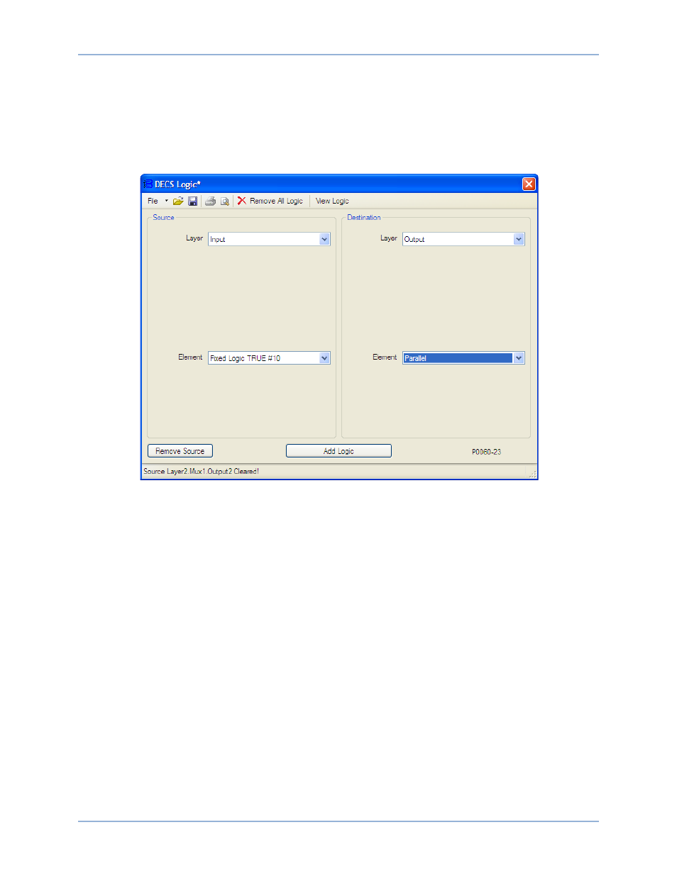
Figure 130 illustrates the DECS Logic window settings associated with this step.
a.
Under Source, select Input as the Layer.
b.
Under Source, select Fixed Logic TRUE #10 as the Element.
c.
Under Destination, select Output as the Layer.
d.
Under Destination, select Parallel as the Element.
e.
Click the Add Logic button.
Figure 130. InputBuffer.Fixed Logic TRUE #10 ---> OutputBuffer.Parallel
5.
Figure 131 illustrates the DECS Logic window settings associated with this step. In the Source portion
of the DECS Logic window:
a.
Select Input from the Layer pull-down menu.
b.
Select Load Comp as the Element.
c.
Click the Remove Source button.
6.
Figure 132 illustrates the DECS Logic window settings associated with this step.
a.
Under Source, select Layer 2 as the Layer.
b.
Under Source, select MUX as the Gate Type.
c.
Under Source, select 1 as the Gate Number.
d.
Under Source, select 2 as the Element.
e.
Under Destination, select Layer 1 as the Layer.
f.
Under Destination, select MUX as the Gate Type.
g.
Under Destination, select 1 as the Gate Number.
h.
Under Destination, select 1 as the Element.
i.
Click the Add Logic button.
7.
Verify the logic scheme modifications by reviewing the logic associations displayed in the DECS
Logic Viewer. (Click the View Logic button in the DECS Logic window.)
DECS-400
Programmable Logic