BECKHOFF CX9020 User Manual
Page 20
Mounting and wiring
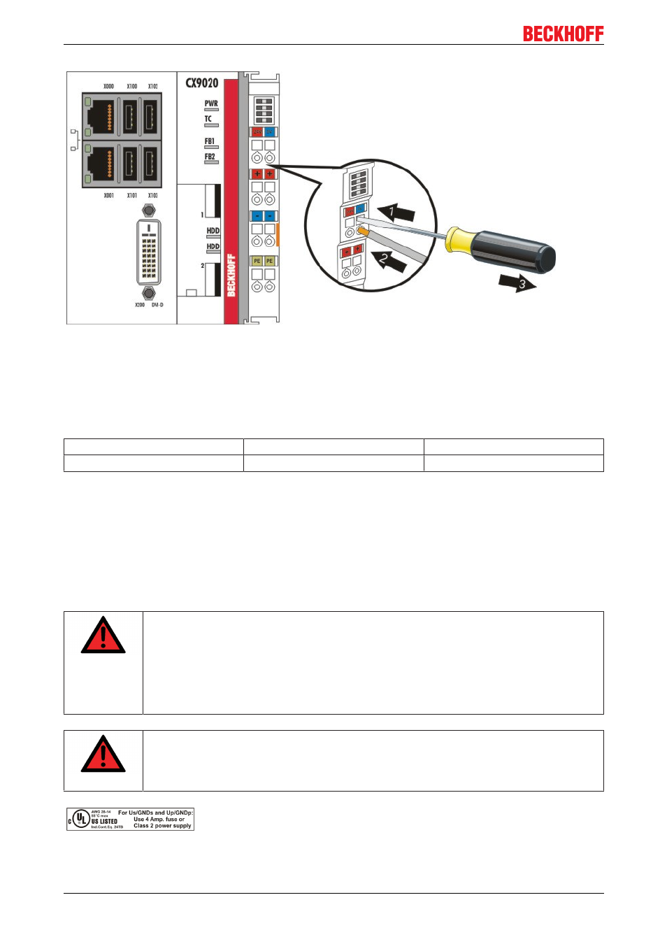
The terminals are implemented in spring force technology. Connect the cables as follows:
1. Open a springloaded terminal by slightly pushing with a screwdriver or a rod into the square opening
above the terminal.
2. The wire can now be inserted into the round terminal opening without any force.
3. The terminal closes automatically when the pressure is released, holding the wire securely and
permanently.
Wire size width
0.5 ... 2.5 mm
2
AWG 20 .. AWG 14
Wire stripping length
8 ... 9 mm
0.33 inch
LED
If the power supply unit is connected correctly and the power supply is switched on, the two upper LEDs in
the terminal prism are green. The left LED (Us) indicates the CPU supply. The right LED (Up) indicates the
terminal supply. The other LEDs indicate the Terminal Bus status. A detailed description of the LEDs can be
found in section "LED troubleshooting".
UL requirements
DANGER
Compliance of the UL requirements
For the compliance of the UL requirements the CXControllers should only be supplied by a
24 VDC supply voltage, supplied by an isolating source and protected by means of a fuse
(in accordance with UL248), rated maximum 4 Amp.by a 24 VDC power source, that has to
satisfy NEC class 2. A NEC class 2 power supply shall not be connected in series or paral
lel with another (class 2) power source!This UL requirements are valid for all supply volt
ages of the CXControllers!
DANGER
Compliance of the UL requirements
To meet the UL requirements, the CXControllers must not be connected to unlimited
power sources!
CX9020
20
Version 1.1