Using a daktronics router, System riser diagrams, For more information – Daktronics DMP-1500/M3 (SS & ST) Setup With Show Control User Manual
Page 11
DMP-1500/M3 (SS & ST) Setup With Show Control Quick Guide
11 of 11
201 Daktronics Drive PO Box 5128, Brookings, SD 57006
Tel: 1-800-325-8766 or 605-697-4300 Fax: 605-697-4746
Website: www.daktronics.com
DD1805670 Rev 11
2 July 2012
11.
After the display has rebooted, close all the open M2 Configuration
windows and use the Venus 1500 software to connect to the display
(refer to Venus 1500 Installation & Configuration).
12.
Now change the IP address of the Show Control computer using the
Network Administrator’s recommended settings.
Using a Daktronics Router
The display(s) must be set up to obtain their IP Addresses automatically.
In most cases, the router will be used to create a network separate from
the facility’s; the router may be configured to connect to such a network.
Note: Do not connect the router to the facility’s network without
reconfiguring it. Refer to the router’s documentation for instructions
on connecting to a facility network.
1.
Follow steps 1-8 under Using Existing Network.
2.
Click Obtain an IP address automatically.
3.
Enter any descriptive DHCP Name (Ex: “East16x112”,
“Primary16x112”, etc.).
4.
Press [F7] to apply the settings.
5.
Verify all computers on the network are set to obtain IP Address
automatically:
a.
Press the Windows key [] and click on Control Panel.
b.
Click on Network and Sharing Center.
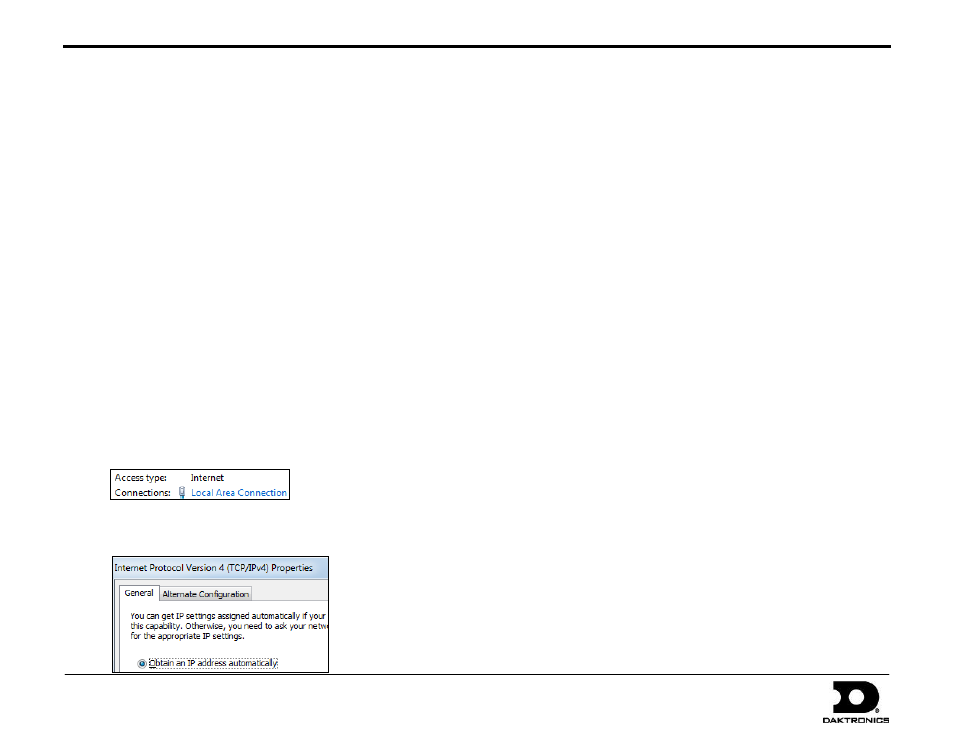
c.
Click Local Area Connection.
d.
Click Properties.
e.
Double-click on Internet Protocol Version 4 (TCP/IPv4).
f.
Verify that Obtain an IP address automatically is selected.
System Riser Diagrams
Refer to the attached drawings for typical layouts of display
communication methods.
Indoor, Wire Ethernet: DWG-835248
Indoor, Fiber Ethernet: DWG-835283
Indoor, Ethernet Bridge Radio: DWG-1065120
Outdoor: Fiber Ethernet: DWG-836336
ST-2014: DWG-808072
ST-2016: DWG-1044507
Control Setup, ST-2014/16: DWG-1037213
For additional system riser diagrams featuring RTD integration
and wireless Ethernet setups, refer to DD1562468.
For More Information
To learn more about the Daktronics Show Control System
software, consult the Show Control System User Handbook,
which is accessible via either of the following options:
Press the Windows key [] and go to All Programs >
Daktronics > Display Studio > Show Control System
User Handbook.
From within Display Studio, press the Display Studio
Hub button and select Help.
For any other questions, comments, or concerns, please contact
Daktronics Support Services.
United States & Canada
Toll Free: 1-800-DAKTRONICS (1-800-325-8766)
Outside the U.S. & Canada
+1-605-697-4000