Chapter 3 – DFI CR960-HM76 User Manual
Page 20
www.dfi .com
Chapter 3 Hardware Installation
20
Chapter 3
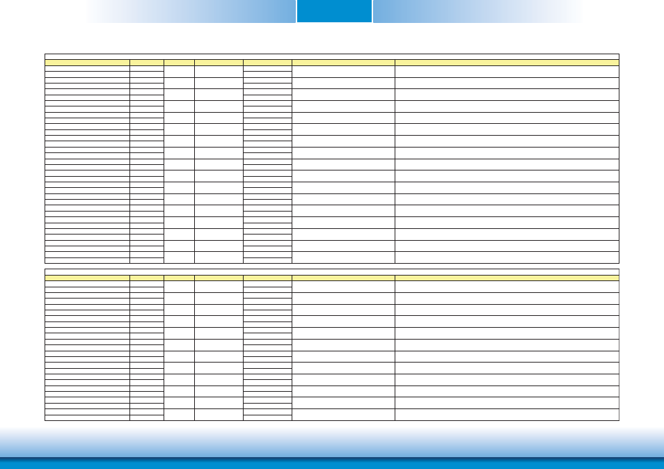
Signal
Pin#
Pin Type
Pwr Rail /Tolerance
CR960
Carrier Board
Description
PCIE_TX0+
A68
AC Coupling capacitor
PCIE_TX0-
A69
AC Coupling capacitor
PCIE_RX0+
B68
PCIE_RX0-
B69
PCIE_TX1+
A64
AC Coupling capacitor
PCIE_TX1-
A65
AC Coupling capacitor
PCIE_RX1+
B64
PCIE_RX1-
B65
PCIE_TX2+
A61
AC Coupling capacitor
PCIE_TX2-
A62
AC Coupling capacitor
PCIE_RX2+
B61
PCIE_RX2-
B62
PCIE_TX3+
A58
AC Coupling capacitor
PCIE_TX3-
A59
AC Coupling capacitor
PCIE_RX3+
B58
PCIE_RX3-
B59
PCIE_TX4+
A55
AC Coupling capacitor
PCIE_TX4-
A56
AC Coupling capacitor
PCIE_RX4+
B55
PCIE_RX4-
B56
PCIE_TX5+
A52
AC Coupling capacitor
PCIE_TX5-
A53
AC Coupling capacitor
PCIE_RX5+
B52
PCIE_RX5-
B53
PCIE_TX6+
D19
AC Coupling capacitor
PCIE_TX6-
D20
AC Coupling capacitor
PCIE_RX6+
C19
PCIE_RX6-
C20
PCIE_TX7+
D22
NA
PCIE_TX7-
D23
NA
PCIE_RX7+
C22
PCIE_RX7-
C23
PCIE0_CK_REF+
A88
PCIE0_CK_REF-
A89
Signal
Pin#
Pin Type
Pwr Rail /Tolerance
CR960
Carrier Board
Description
PEG_TX0+
D52
AC Coupling capacitor
PEG_TX0-
D53
AC Coupling capacitor
PEG_RX0+
C52
PEG_RX0-
C53
PEG_TX1+
D55
AC Coupling capacitor
PEG_TX1-
D56
AC Coupling capacitor
PEG_RX1+
C55
PEG_RX1-
C56
PEG_TX2+
D58
AC Coupling capacitor
PEG_TX2-
D59
AC Coupling capacitor
PEG_RX2+
C58
PEG_RX2-
C59
PEG_TX3+
D61
AC Coupling capacitor
PEG_TX3-
D62
AC Coupling capacitor
PEG_RX3+
C61
PEG_RX3-
C62
PEG_TX4+
D65
AC Coupling capacitor
PEG_TX4-
D66
AC Coupling capacitor
PEG_RX4+
C65
PEG_RX4-
C66
PEG_TX5+
D68
AC Coupling capacitor
PEG_TX5-
D69
AC Coupling capacitor
PEG_RX5+
C68
PEG_RX5-
C69
Connect to PCIE device or slot
Device - Connect AC Coupling cap 0.1uF
Slot - Connect to PCIE Conn pin
Device - Connect AC Coupling cap 0.1uF
Slot - Connect to PCIE Conn pin
Connect to PCIE device or slot
Device - Connect AC Coupling cap 0.1uF
Slot - Connect to PCIE Conn pin
Device - Connect AC Coupling cap 0.1uF
Slot - Connect to PCIE Conn pin
Connect to PCIE device or slot
Connect to PCIE device or slot
Device - Connect AC Coupling cap 0.1uF
Slot - Connect to PCIE Conn pin
NA
NA
Connect to PCIE device, PCIe CLK Buffer or slot
Connect to PCIE device or slot
Connect to PCIE device or slot
Device - Connect AC Coupling cap 0.1uF
Slot - Connect to PCIE Conn pin
Device - Connect AC Coupling cap 0.1uF
Slot - Connect to PCIE Conn pin
Connect to PCIE device or slot
I PCIE
AC coupled off Module
PCI Express Graphics receive differential pairs 5
Connect AC Coupling cap 0.22uF
O PCIE
AC coupled on Module
PCI Express Graphics transmit differential pairs 5
Connect to PCIE device or slot
PCI Express Graphics transmit differential pairs 4
I PCIE
AC coupled off Module
I PCIE
AC coupled off Module
PCI Express Graphics receive differential pairs 3
I PCIE
AC coupled off Module
PCI Express Graphics receive differential pairs 2
O PCIE
AC coupled on Module
PCI Express Graphics transmit differential pairs 3
PCI Express Graphics receive differential pairs 4
O PCIE
AC coupled on Module
Connect AC Coupling cap 0.22uF
Connect to PCIE device or slot
Connect AC Coupling cap 0.22uF
Connect to PCIE device or slot
Connect AC Coupling cap 0.22uF
O PCIE
AC coupled on Module
I PCIE
PCI Express Graphics transmit differential pairs 2
PEG Signals Descriptions
O PCIE
AC coupled on Module
PCI Express Graphics transmit differential pairs 0
I PCIE
AC coupled off Module
PCI Express Graphics receive differential pairs 0
O PCIE
AC coupled on Module
PCI Express Graphics transmit differential pairs 1
AC coupled off Module
PCI Express Graphics receive differential pairs 1
Connect to PCIE device or slot
Connect AC Coupling cap 0.22uF
Connect to PCIE device or slot
Connect AC Coupling cap 0.22uF
Connect to PCIE device or slot
I PCIE
AC coupled off Module
I PCIE
AC coupled off Module
O PCIE
AC coupled on Module
PCI Express Differential Receive Pairs 7
(Optional with on board LAN, Default setting as NC)
O PCIE
PCIE
Reference clock output for all PCI Express and PCI Express Graphics
lanes.
PCI Express Differential Receive Pairs 6
O PCIE
AC coupled on Module
PCI Express Differential Transmit Pairs 7
(Optional with on board LAN, Default setting as NC)
PCI Express Differential Transmit Pairs 4
PCI Express Differential Receive Pairs 2
PCI Express Differential Transmit Pairs 6
PCI Express Differential Transmit Pairs 3
I PCIE
AC coupled off Module
PCI Express Differential Receive Pairs 5
I PCIE
AC coupled off Module
O PCIE
AC coupled on Module
PCI Express Differential Transmit Pairs 5
I PCIE
AC coupled off Module
PCI Express Differential Receive Pairs 4
O PCIE
AC coupled on Module
O PCIE
AC coupled on Module
O PCIE
AC coupled on Module
PCI Express Differential Transmit Pairs 1
PCI Express Differential Receive Pairs 1
PCI Express Differential Receive Pairs 3
O PCIE
AC coupled on Module
PCI Express Differential Transmit Pairs 0
O PCIE
AC coupled on Module
PCI Express Differential Transmit Pairs 2
I PCIE
AC coupled off Module
I PCIE
AC coupled off Module
PCI Express Differential Receive Pairs 0
I PCIE
AC coupled off Module
PCI Express Lanes Signals Descriptions