Chapter 3 – DFI HM961-HM86 User Manual
Page 32
Advertising
www.dfi .com
Chapter 3 Hardware Installation
32
Chapter 3
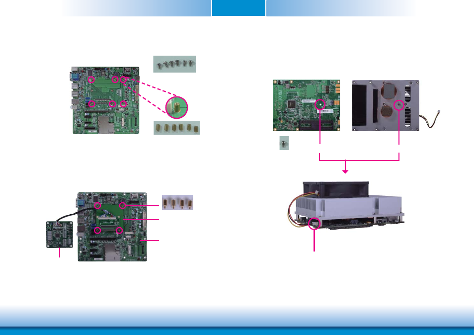
3. Fasten bolts with mounting screws through mounting holes to be fixed in place.
4. Use the provided bolts to fix the COMe-LINK1 debug card onto the carrier board.
Bolts
COMe-LINK1
Carrier Board
Fan connector
Mounting
screw
5. Align the mounting hole on the heat sink with the mounting hole on the module and
secure the heat sink onto the module by a mounting screw from the bottom side of the
module.
Mounting hol
e
Mounting hole
Bottom side of heat sink
Bottom side of module
Bolts
Mounting screws
COMe-DEBUG
Advertising
This manual is related to the following products: