Chapter 2 – DFI FS700 User Manual
Page 13
www.dfi .com
Chapter 2 Hardware Installation
13
Chapter 2
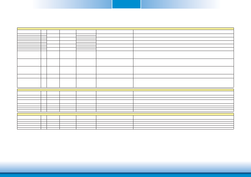
Signal
Pin#
Pin Type
Pwr Rail /Tolerance
DFI-FS700 Series
Carrier Board
Description
USB_P0+
96
USB_P0-
94
USB_P1+
95
USB_P1-
93
USB_P2+
90
USB_P2-
88
USB_P3+
89
USB_P3-
87
USB_P4+
84
USB_P4-
82
USB_0_1_OC#
86
I CMOS
3.3V Suspend/3.3V
PU 10k to 3.3VSB
Connect to Overcurrent of USB Power Switch
USB over-current sense, USB channels 0 and 1. A pull-up for this line shall be present on the Module. An open drain driver from a USB current monitor on the Carrier Board may drive this line
low.
Do not pull this line high on the Carrier Board.
USB_2_3_OC#
85
I CMOS
3.3V Suspend/3.3V
PU 10k to 3.3VSB
Connect to Overcurrent of USB Power Switch
USB over-current sense, USB channels 0 and 1. A pull-up for this line shall be present on the Module. An open drain driver from a USB current monitor on the Carrier Board may drive this line
low.
Do not pull this line high on the Carrier Board.
USB_4_5_OC#
80
I CMOS
3.3V Suspend/3.3V
PU 10k to 3.3VSB
Connect to Overcurrent of USB Power Switch
USB over-current sense, USB channels 0 and 1.
A pull-up for this line shall be present on the Module. An open drain driver from a USB current monitor on the Carrier Board may drive this line low.
Do not pull this line high on the Carrier Board.
USB_ID
92
I CMOS
3.3V Suspend/3.3V
USB ID pin.Configures the mode of the USB Port 1. If the signal is detected as being 'high active' the BIOS will automatically configure USB Port 1 as USB Client and enable USB Client support.
This signal should be driven as OC signal by external circuitry.
USB_CC
91
I CMOS
3.3V Suspend/3.3V
USB Client Connect pin.If USB Port 1 is configured for client mode then an externally connected USB host should set this signal to high-active in order to properly make the connection with the
module's internal USB client controller.
If the external USB host is disconnected, this signal should be set to low-active in order to inform the USB client controller that the external host has been disconnected.
A level shifter/protection circuitry should be implemented on the carrier board for this signal.
Signal
Pin#
Pin Type
Pwr Rail /Tolerance
DFI-FS700 Series
Carrier Board
Description
SDIO_CD#
43
I/O CMOS
3.3V/3.3V
SDIO Card Detect. This signal indicates when a SDIO/MMC card is present.
SDIO_CLK
42
O CMOS
3.3V/3.3V
SDIO Clock. With each cycle of this signal a one-bit transfer on the command and each data line occurs. This signal has maximum frequency of 48 MHz.
SDIO_CMD
45
I/O OD/PP CMOS
3.3V/3.3V
SDIO Command/Response. This signal is used for card initialization and for command transfers. During initialization mode this signal is open drain. During command transfer this signal is in push-
pull mode.
SDIO_LED
44
O CMOS
3.3V/3.3V
SDIO LED. Used to drive an external LED to indicate when transfers occur on the bus.
SDIO_WP
46
I/O CMOS
3.3V/3.3V
SDIO Write Protect. This signal denotes the state of the write-protect tab on SD cards.
SDIO_PWR#
47
O CMOS
3.3V/3.3V
SDIO Power Enable. This signal is used to enable the power being supplied to a SD/MMC card device.
SDIO_DAT0-7
48-55
I/O PP CMOS
3.3V/3.3V
SDIO Data lines. These signals operate in push-pull mode
Signal
Pin#
Pin Type
Pwr Rail /Tolerance
DFI-FS700 Series
Carrier Board
Description
I2S_CLK
61
O CMOS
3.3V/3.3V
I2S Clock outout
I2S_TXFS
59
O CMOS
3.3V/3.3V
I2S TXFS
I2C_TXC
63
O CMOS
3.3V/3.3V
I2C TXC
I2S_TXD
67
O CMOS
3.3V/3.3V
I2S TXD
I2S_RXD
65
I CMOS
3.3V/3.3V
I2 RXD
Connect 90ಳ @100MHz Common Choke in series and ESD
suppressors to GND to USB connector
Connect 90ಳ @100MHz Common Choke in series and ESD
suppressors to GND to USB connector
Connect 90ಳ @100MHz Common Choke in series and ESD
suppressors to GND to USB connector
Universal Serial Bus Port 3 differential pair.
I/O USB
I/O USB
I/O USB
I/O USB
Universal Serial Bus Port 1 differential pair.This port may be optionally used as USB client port.
Universal Serial Bus Port 4 differential pair.
3.3V Suspend/3.3V
3.3V Suspend/3.3V
Connect 90ಳ @100MHz Common Choke in series and ESD
suppressors to GND to USB connector
Connect 90ಳ @100MHz Common Choke in series and ESD
suppressors to GND to USB connector
SDIO Interface Signals
High Definition Audio Signals/AC'97
3.3V Suspend/3.3V
3.3V Suspend/3.3V
3.3V Suspend/3.3V
USB Interface Signals
Universal Serial Bus Port 0 differential pair.
I/O USB
Universal Serial Bus Port 2 differential pair.