Chapter 2 - hardware installation, Board layout, Block diagram – DFI FS700 User Manual
Page 8: Freescale i.mx6, Amxm golden finger, Usb hub, Pmic
Advertising
www.dfi .com
Chapter 2 Hardware Installation
8
Chapter 2
Chapter 2 - Hardware Installation
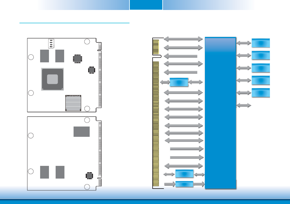
Board Layout
Top View
Bottom View
PMIC
MMPF0100
USB HUB
USB2514BI
Freescale
i.MX6 Series
1
ON
234
microSD
Boot Device Select
(Switch)
DDR3
DDR3
Block Diagram
DDR3
DDR3
eMMC
Atheros
AR8033
DDR3
Freescale
i.MX6
AMXM Golden Finger
24 bits LVDS
Backlight
I
2
C 2
HDMI
USB OTG
SDIO (SD3)
SATA
CAN Bus
PCIe
24 bits LVDS
Backlight
I C 2
24 bits LVDS
HDMI
24 bits LVDS
USB OTG
SDIO (SD3)
SATA
SDIO (SD3)
CAN Bus
PCIe
HDA (I
2
S)
USB Hub
USB 0-3
USB
eMMC
micro SD
SD4
SD2
Sensor
I
2
C
Camera
MIPI CSI
UART1
GLAN PHY
RGMII
MDI
SPI 1
SPI 1
UART5
UART5
Power ON
Power ON
Reset
Reset
Power
PMIC
Power
Power
Power
P
Advertising