Chapter 2 – DFI Q7-100 User Manual
Page 23
www.dfi.com
Chapter 2 Hardware Installation
23
Chapter 2
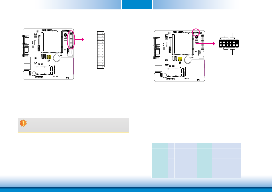
Power Connectors
Use a power supply that complies with the ATX12V Power Supply Design Guide Version 1.1.
An ATX12V power supply unit has a standard 24-pin ATX main power connector that must be
inserted into the 24-pin connector. The 8-pin +12V power connector enables the delivery of
more +12VDC current to the processor’s Voltage Regulator Module (VRM).
The power connectors from the power supply unit are designed to fit the 24-pin and 8-pin
connectors in only one orientation. Make sure to find the proper orientation before plugging
the connectors.
The system board requires a minimum of 300 Watt power supply to operate. Your system
configuration (CPU power, amount of memory, add-in cards, peripherals, etc.) may exceed the
minimum power requirement. To ensure that adequate power is provided, we strongly recom-
mend that you use a minimum of 400 Watt (or greater) power supply.
13
12 24
1
PWR_OK
+5VSB
+12VDC
+3.3VDC
-12VDC
Ground
PS_ON#
NC
+5VDC
+5VDC
ATX power
Ground
Ground
Ground
+5VDC
Ground
+3.3VDC
+3.3VDC
Ground
+5VDC
Ground
+5VDC
Ground
+12VDC
+3.3VDC
Front Panel Connectors
HDD-LED - HDD LED
This LED will light when the hard drive is being accessed.
RESET SW - Reset Switch
This switch allows you to reboot without having to power off the system.
PWR-BTN - Power Switch
This switch is used to power on or off the system.
PWR-LED - Power/Standby LED
When the system’s power is on, this LED will light. When the system is in the S1 (POS - Power
On Suspend) state, it will blink every second. When the system is in the S3 (STR - Suspend To
RAM) state, it will blink every 4 seconds.
1
2
11
12
HDD-LED
RESET-SW
PWR-LED
PWR-BTN
Pin Pin Assignment
Pin Pin Assignment
N.C.
1
N.C.
PWR-LED
2
LED Power
HDD-LED
3
HDD Power
Signal
4
LED Power
5
6
Signal
RESET SW
7
Ground
RST Signal
PWR-BTN
8
Signal
9
10
Ground
N.C.
11 N.C.
Key
12
Key
Important:
Insufficient power supplied to the system may result in instability or the add-in
boards and peripherals not functioning properly. Calculating the system’s approxi-
mate power usage is important to ensure that the power supply meets the sys-
tem’s consumption requirements.