Installation – Fire Magic 3287-1(P) Searing Station Built in User Manual
Page 6
GAS-SUPPLY PLUMBING REQUIREMENTS
Rigid
1/2
" black steel pipe is required to conduct the gas supply into the masonry opening for connection to the
unit. Apply pipe joint compound (resistant to all gasses) to all male pipe fi ttings and tighten all joints securely. Do
not use pipe joint compound to connect fl are fi ttings. The pipe should enter the enclosure either from the bottom
or from any side at least 13" below the countertop.
Note: Any protrusion into the enclosure higher than 13" below countertop will obstruct the frame
and prevent the unit from dropping into place.
Note: An external valve (with a removable key) in the gas line is recommended for safety.
GAS-SUPPLY AND MANIFOLD PRESSURES
For natural gas: Normal 7" water column, minimum 5", maximum 10-
1/2
". For propane gas: Normal 11" water
column, minimum 10", maximum 13". A REGULATOR MUST BE PROVIDED AT THE GAS SOURCE FOR USE
WITH PROPANE GAS.
CHECKING FUEL AND ORIFICES
The Fire Magic
®
Searing Station is equipped with orifi ces for natural
gas unless otherwise indicated. For propane gas, smaller orifi ces
must be installed to avoid hazardous overheating. (Please refer to
Table 1 for the correct orifi ce size.) Check the orifi ce size by following
the instructions below. The drill size is stamped on the orifi ce. If the
number is not visible, you may have to remove the orifi ce (as detailed
below) to read the number stamped on the side of the orifi ce.
When converting the unit, follow the steps below:
1. Remove the Searing Station lid and lift off the cooking grid.
2. Remove the control knob and screws fi rst, and then carefully
lift away the control panel. This allows access to the regulator
(see next page).
Important: Prior to fully removing the control panel, you must
disconnect the battery holder assembly wires that are
located behind the control panel.
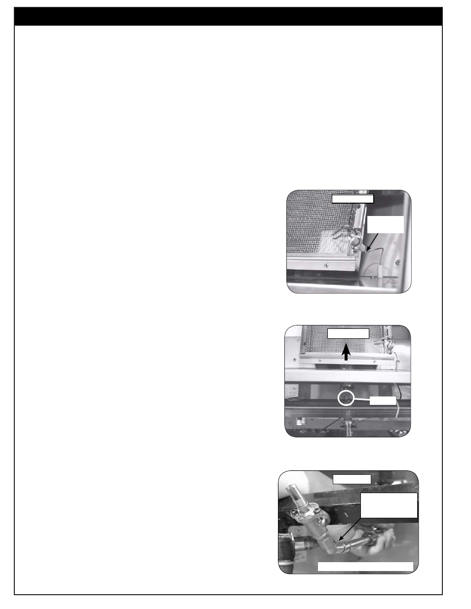
3. Pull the wire from the bottom of the electrode attached to the
burner (Fig. 6-1) and carefully lift the burner up, allowing the
tabs to clear the slots in the rear burner rest. Pull the gas-
supply tube away from the orifi ce (see Fig. 5-2) located inside
the circular opening in the front fi rewall of the unit.
4. Using
a
3/8
" socket, remove the orifi ce from the orifi ce holder
(see Fig. 6-3) and check the number stamped on the face.
5. If an orifi ce change is necessary, replace the orifi ce with the
correct-sized one.
6. Replace the gas-supply tube over the orifi ce, aligning the
burner into the rear burner rest. Re attach the electrode wire.
Note: The regulator and gas connection elbow are located
behind the control panel. For conversion / gas hook
up; see the CONVERTING THE REGULATOR and/or
CONNECTING THE GAS SUPPLY sections before
replacing the control panel.
7 . Replace the control panel, being sure to reconnect the battery
holder assembly wires. Replace the control knob, cooking
grid and lid.
INSTALLATION
Fig. 6-1
Remove
connector
Fig. 6-3
Orifi ce is located
at the end of the
valve
Firewall removed for clarity.
Orifi ce
Fig. 6-2
6
L-C2-200
Rev 10 - 1401131145