Fire Magic 3287-1(P) Searing Station Built in User Manual
Page 7
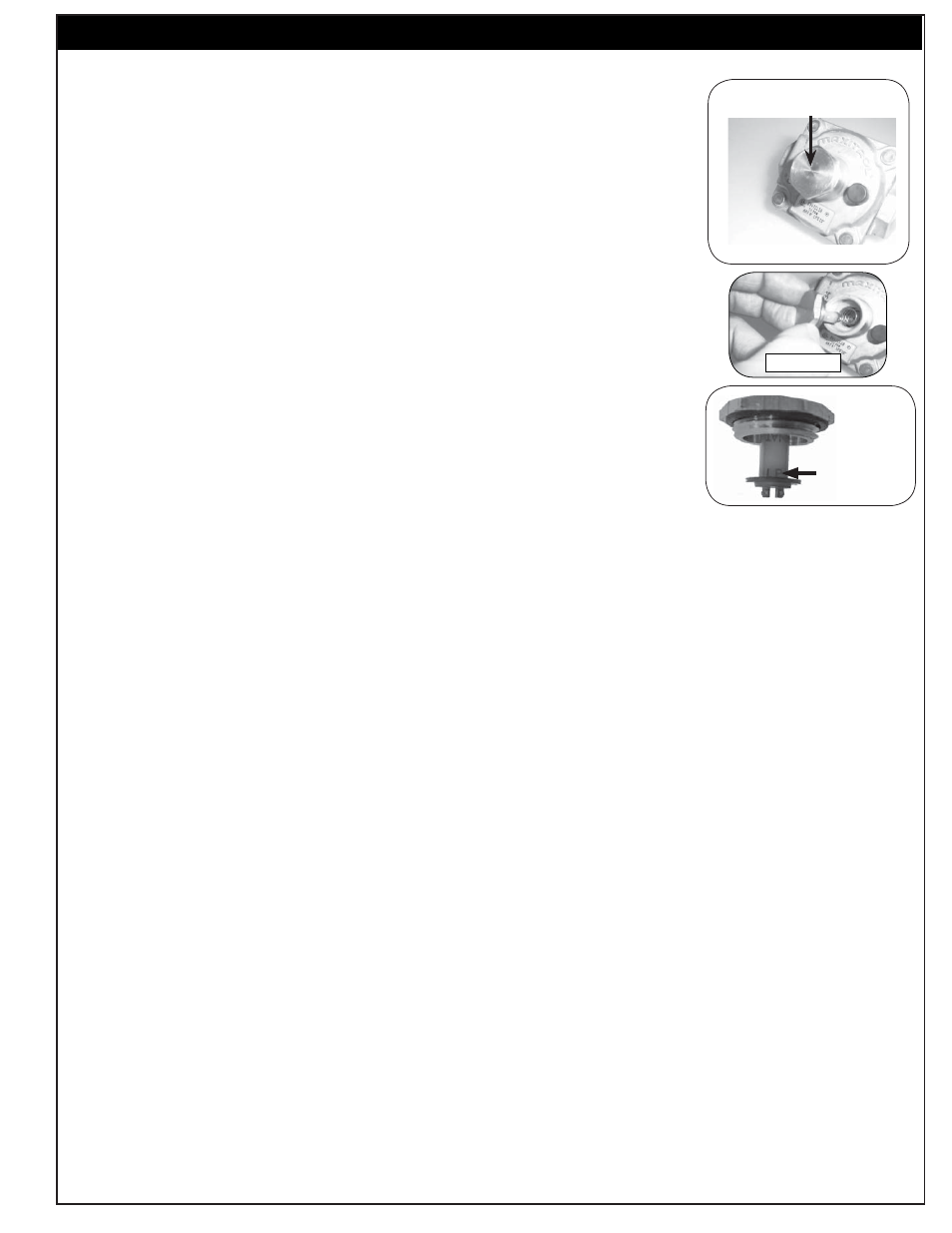
CONVERTING THE REGULATOR
1. Unscrew and remove the cap from the regulator, extracting the converter (Fig.
7-1).
2. Remove the converter (the plastic stalk) by carefully pulling it away from the
center of the cap (it will snap out of its seating); see Fig. 7-2.
3. Turn the converter around and replace it carefully into the center of the cap
(it will snap into place). Check that you can read (at the bottom of the stalk)
the gas type the unit is set to use (Fig. 7-3).
4. Replace the unit into the regulator and screw down until snug. Do not over-
tighten.
CONNECTING THE GAS SUPPLY
1. The burner manifold has a
1/2
" male fl are fi tting gas inlet elbow. A
1/2
" female
fl are fi tting connector nut is required to hook the gas supply to the burner.
2 . Use a stainless-steel fl ex connector to bring the gas supply from the gas-line
stub or propane-gas tank to the Searing Station manifold. A
1/2
" x 24" or 36"
fl ex connector is suitable for most installations.
CAUTION: Use only a C.S.A.-listed stainless-steel fl ex connector. Do not
use a rubber hose or plastic hose within the enclosure for the
Searing Station; it will leak, resulting in an explosion and/or
serious injury.
3. Be sure the gas supply is off. Connect the pipe adapter fi tting supplied with the fl ex connector to the gas-
supply stub. Use pipe joint compound that is resistant to all gasses on the pipe fi tting. Tighten the fi tting
to the gas supply and connector fl are nut securely.
Note: Pipe joint compound should not be used on fl are fi tting connections.
4. Connect the fl ex connector fl are nut to the Searing Station manifold elbow fl are fi tting. Be sure to tighten
securely. Use a second wrench to support the manifold to avoid damaging the manifold.
5. Slide the unit into the enclosure and replace the control panel.
LEAK TESTING
Carefully turn on the gas supply and leak test at all connections with a soapy water solution (equal parts
liquid detergent and water). If bubbles appear, a leak is present. Turn off gas and tighten connections, turn
INSTALLATION ( C o n t . )
Read gas
type here
Fig. 7-3
Fig. 7-1
Regulator
Note the cap on top
Fig. 7-2
7
L-C2-200
Rev 10 - 1401131145