Figure 1: logix 510si principle of operation – Flowserve 510si IOM Logix User Manual
Page 6
6
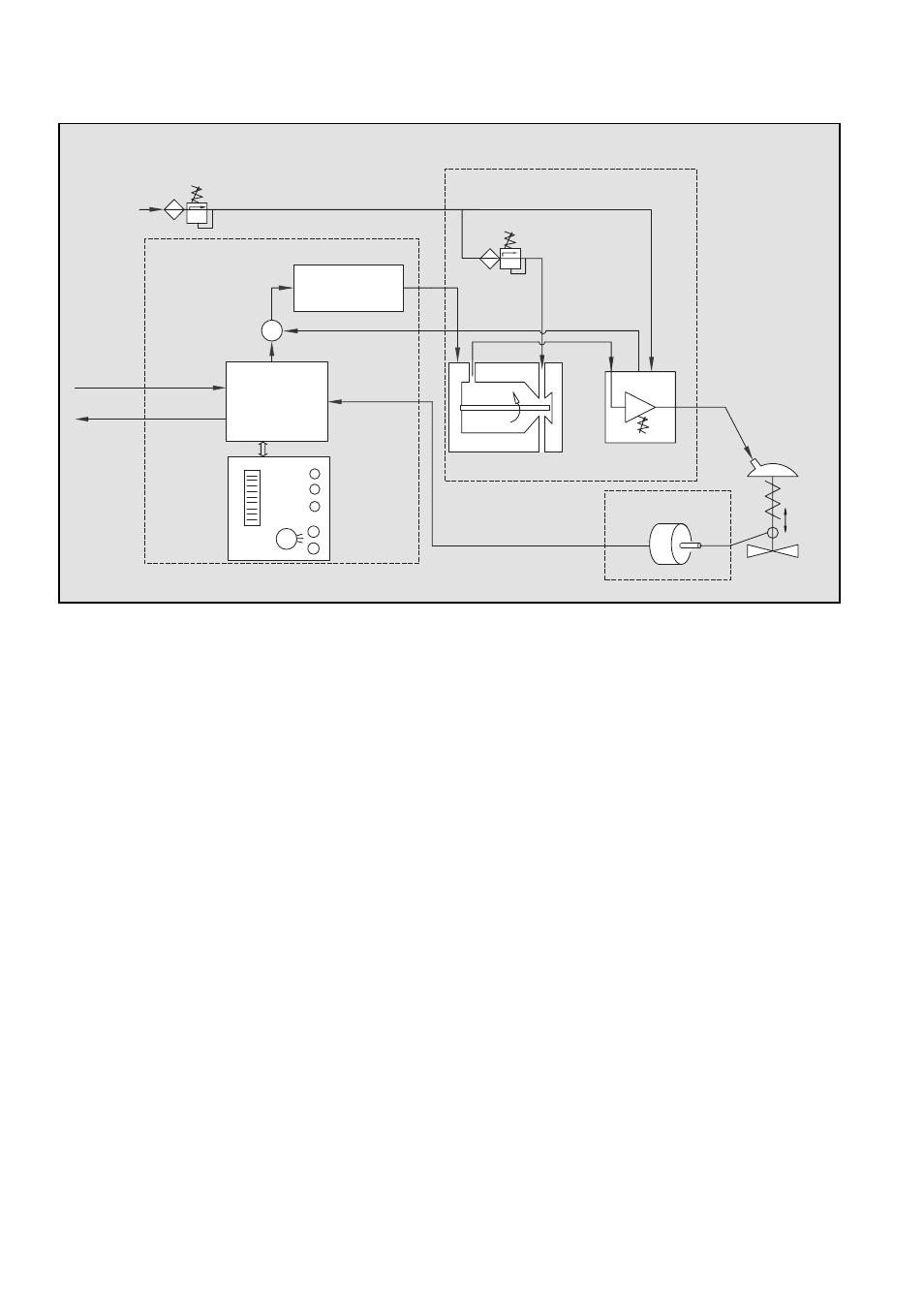
Figure 1: Logix 510si Principle of Operation
5
PRINCIPLE OF OPERATION
The Logix 510si positioner is a digital positioner with
various options. The positioner consists of three main
modules:
1.
The microprocessor-based electronic control
module includes direct local user interface
switches
2.
The piezo valve-based electro-pneumatic con
verter module
3.
The infinite resolution valve position sensor.
The basic positioner operation is best understood by
referring to Figure 1. The complete control circuit is
powered by the two-wire, 4-20 mA command signal.
The analog 4-20 mA command is passed to the mi-
croprocessor, where it is compared to the measured
valve stem position. The control algorithm in the proc-
essor performs control calculations and produces an
output command to the piezo valve, which drives the
pneumatic amplifier. The position of the pilot valve in
the pneumatic amplifier is measured and relayed to
the inner loop control circuit. This two-stage control
provides for more responsive and tighter control than
is possible with a single stage control algorithm. The
pneumatic amplifier controls the airflow to the actua-
tor. The change of pressure and volume of the air in
the actuator causes the valve to stroke. As the valve
ap
6
TUBING POSITIONER TO ACTUATOR
After mounting has been completed, tube the
positioner to the actuator using the appropriate com-
pression fitting connectors:
Air connections: 1/4” NPT (standard air connec-
tion)
Auxiliary power: Pressurized air or permissible
gases, free of moisture and dust in according with
IEC 770 or ISA 7.0.01.
Pressure range: 1,5 – 6,0 bar (22 – 87 psi)
For connecting the air piping, the following notes
should be observed:
1.
The positioner passageways are equipped with
filters, which remove medium and coarse size
dirt from the pressurized air. If necessary, they
are easily accessible for cleaning.
2.
Supply air should meet IEC 770 or ISA 7.0.01
requirements. A coalescing filter should be
installed in front of the supply air connection Z.
Now connect the air supply to the filter, which
is connected to the Logix 500 Series positioner.
3.
With a maximum supply pressure of 6 bar
(87 psi) a regulator is not required.
4.
With an operating pressure of more than
6 bar (87 psi), a reducing regulator is required.
The flow capacity of the regulator must be
larger than the air consumption of the positioner
(7 Nm
3
/h @ 6 bar / 4,12 scfm @ 87 psi).
Local
User
Interface
4 – 20 mA
Inner Loop
Piezo Control
Stroke
Inner Loop
Position Feedback
1 Digital Control Circuit
2 Electro-pneumatic
Converter Module
3 Valve
Position
Sensor
Filter / Regulator
for Supply Air
1.5 – 6.0 bar (22 – 87 psi)
Air Supply
∑
-
Micro-
Processor
Gain
Pressure Regulator
Piezo Valve
Pneumatic
Amplifier
Control Valve
+
4 – 20 mA
Input
Output
(0ptional)