Flowserve 510si IOM Logix User Manual
Page 8
8
Electromagnetic Compatibility
The Logix 510si digital positioner has been designed
to operate correctly in electromagnetic (EM) fields
found in typical industrial environments. Care should
be taken to prevent the positioner from being used
in environments with excessively high EM field
strengths (greater than 10 V/m). Portable EM devices
such as hand-held two-way radios should not be used
within 30 cm of the device.
Ensure proper wiring and shielding techniques of the
control lines, and route control lines away from elec-
tromagnetic sources that may cause unwanted noise.
An electromagnetic line filter can be used to further
eliminate noise (FLOWSERVE Part Number
10156843).
In the event of a severe electrostatic discharge near
the positioner, the device should be inspected to
ensure correct operability. It may be necessary to
recalibrate the Logix 510si positioner to restore
operation.
8
STARTUP
8.1
Logix 510si Local Interface Operation
The Logix 510si local user interface allows the user
to fully configure the operation of the positioner, tune
the response, and calibrate the positioner. The Local
interface consists of a quick calibration button for
automatic zero and span setting, along with two jog
buttons for manually spanning the positioner, or for
local Jogging of the valve. There is also a switch block
containing 8 switches. Five of the switches are for
basic configuration settings, three are for calibration
options There is also a rotary selector switch for ad-
justing the positioner gain settings. A 4-20 current
loop calibration button is accessed through a hole in
the cover next to the bottom dipswitch. For indica-
tion of the operational status or alarm conditions there
are 3 LEDs on the local user interface. This docu-
ment describes the setting and use of the Logix 510si
user interface.
8.2
Initial DIP Switch Setting
Before placing the unit in service, set the dipswitches
in the Configuration and Cal boxes to the desired
control options. For a detailed description of each
dipswitch setting, see sections 1&2.
NOTE:
The switch settings in the Configuration box
are activated only by pressing the Quick-Cal button.
Operation of Configuration Dipswitch Setup -The
first 5 Dip Switches are for basic configuration.
a.
Air Action - This must be set to match the configura-
tion of the valve/actuator mechanical tubing connec-
tion and spring location since these determine the air
action of the system.
•
ATO (air-to-open)- Selecting ATO if increasing
output pressure from the positioner is tubed so
it will cause the valve to open.
•
ATC (air-to-close)- Selecting ATC if increasing
output pressure from the positioner is tubed so
it will cause the valve to close.
b.
Signal at Closed - Normally this will be set to 4 mA
for an Air-to-open actuator, and 20 mA for an Air-to-
close actuator configuration.
•
Selecting 4 mA will make the valve fully closed
when the signal is 4mA and fully open when the
signal is 20 mA.
•
Selecting 20 mA will make the valve fully closed
when the signal is 20 mA and fully open when
the signal is 4 mA.
c.
Characteristic
•
Select Linear if the actuator position should be
directly proportional to the input signal.
•
The =% option will characterize the actuator
response to the input signal based on a stan-
dard 30:1 equal percent rangability curve.
d.
Tight Shutoff
•
Select On to have the positioner fully saturate
the actuator closed at a signal less than 1%.
•
Setting the switch in the Off position disables
this feature.
e.
Auto Tune -This switch controls whether the posi-
tioner will auto tune itself every time the quick cal
button is pressed
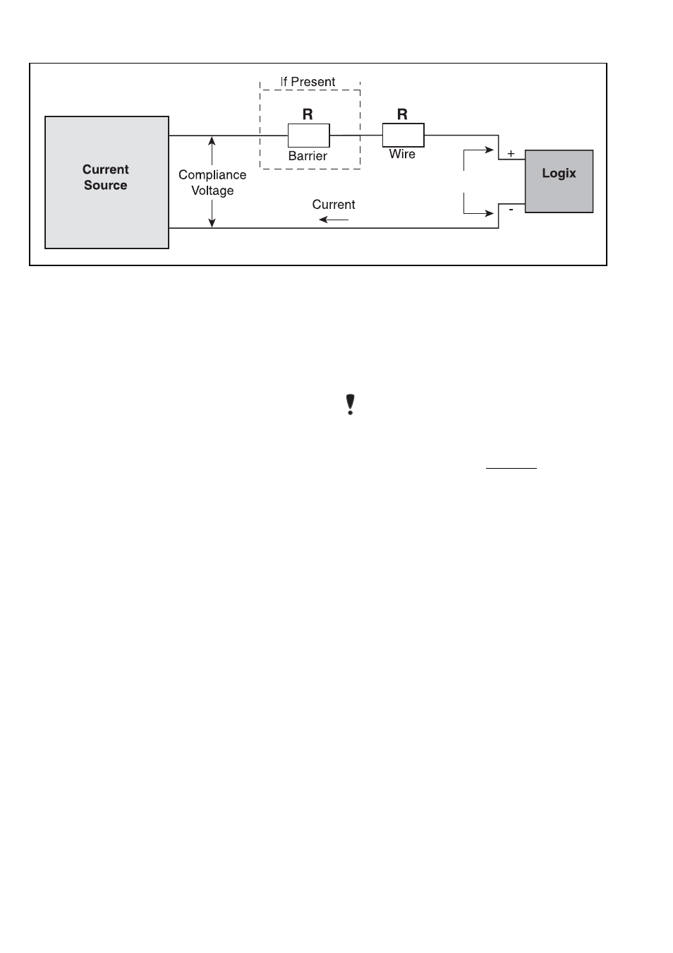
Figure 3: Compliance Voltage
12.0 VDC
510
6.0
si