Flowserve 510si IOM Logix User Manual
Page 9
9
•
On enables an automatic tuning feature that will
automatically determine the positioner gain set-
tings every time a “Quick-Cal” is performed.
The gain settings can be modified after a cali-
bration by adjusting the rotary “Gain” switch.
Note:
there is a small black arrow indicating the
selection. The slot does not indicate the chosen gain.
•
If the rotary “Gain” selector switch is set to “E”
with the auto tune switch on, a Flowserve stan-
dard response tuning set will be calculated and
used.
•
If the rotary “Gain” selector switch is set to “D”,
“C”, “B”, or “A” with the auto tune switch on,
progressively lower gain settings will be calcu-
lated and used.
•
If the rotary “Gain” selector switch is set to “F”,
“G”, or “H” with the auto tune switch on,
progressively higher gain settings will be calcu-
lated and used.
•
Off forces the positioner to use one of the
factory preset tuning sets determined by the
rotary “Gain” selector switch. Settings “A”
through “H” are progressively higher gain pre
defined tuning sets.
8.3
Setup of the Cal Dipswitches - The last 3 Dip Switches
are for calibration configuration.
a.
Quick calibration operating mode.
•
Select Auto if the valve/actuator assembly has
an internal stop in the open and closed posi-
tions. In Auto mode the positioner will fully
close the valve and register the 0% position and
then open the valve to the stop to register the
100% position when performing a self-calibra-
tion. See detailed instructions in section 10.4
on how to perform an auto positioner calibra-
tion.
•
Select Jog if the valve/actuator assembly
has no calibration stop in the open position and
or if you want to manually set the closed posi-
tion. In the Jog mode the positioner waits for
the user to set the open and closed positions
using the Jog buttons labeled with the
∆
and
∇
arrows. See the detailed instructions in section
10.4 on how to perform a manual calibration
using the “Jog” buttons.
b.
Stability Switch – This switch adjusts the position
control algorithm of the positioner for use with low
friction control valves or high friction automated
valves.
•
Placing the switch to the left optimizes the re-
sponse for low friction, high performance con-
trol valves. This setting provides for optimum
response times when used with most low fric-
tion control valves.
•
Placing the switch to the right optimizes the
response for valves and actuators with high
friction levels. This setting slightly slows the
response and will normally stop limit cycling
that can occur on high friction valves.
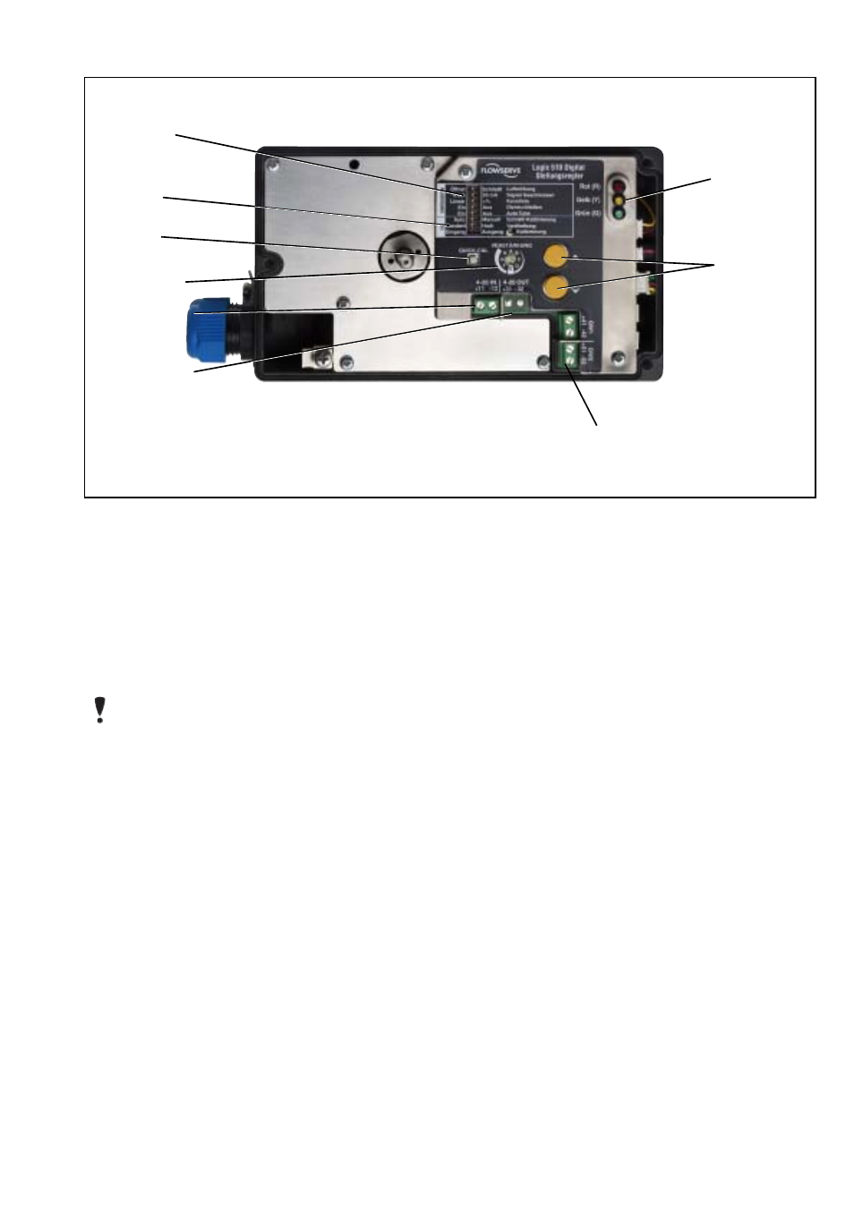
Figure 4: Logix 510si Local Interface
Configuration
Switches
Gain selector
4-20 mA Input
Optional 4-20,mA
Feedback
Terminals for Optional Limit Switches
Jog Calibrate
Buttons
LED Status
Lights
Quick-Cal
Switch
Calibration
Switches