Flowserve Modutronic 20 II Modulating Position Controlle User Manual
Page 26
Limitorque Actuation Systems Modutronic 20 II FCD LMENIM4002-00 – 08/06
26
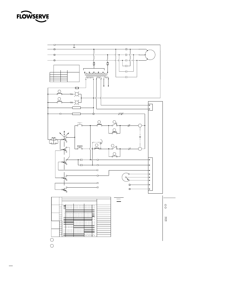
Figure 8.1 – Modutronic 20 II Typical Three-Phase Wiring Diagram
G
Green indicating
R
Red indicating
- Opening coil
- Closing coil
Motor
7
3
(7) (7C)
(3) (3C)
R
G
(18) (18C)
(17) (17C)
(5) (5C)
(1) (1C)
(8) (8C)
8
1
Local
Remote
O
C
O
C
C
C
C
O
O
O
T1
T2
T3
L1
L2
L3
4
5
(4) (4C)
Th.O l
By-pass cir.
Ind light
Open limit
By-pass cir
Ind light
Close limit
Spare
Spare
Spare
Spare
Spare
Spare
Spare
Spare
Fully
Open
Fully
Closed
Valve shown in full open position
Ss
Off
Spare
Spare
3. See certification sheet for voltage supplied.
Transformer unused wired to be separately
covered with insulating heat shrink tubing.
Jump
See note#5
A
B
Gnd
Cpt
18V
115V
18V
Pb1
Open
Pb2
Stop
Pb3
Close
Elec htr
Mtr htr
O
C
(Open)
4
2
(Close)
3
(Common )
1
11
12
13
H2
H1
6
5
Remote ind
Remote ind
21/22
10
19/20
A
B
C
D
E
4-20 mA
Input
Signal
(+)
(-)
Blue
Yellow
Orange
1000
ohm
Pot
10
9
8
7
6
5
4
3
1
2
Open
Close
Common
CW
Sweeper
CCW
(+)
(-)
Input Signal
18 VAC
Power
18
1
Yellow
Blue
Orange
17
18
LEGEND
2.
1.
Close contact
Open contact
NOTES
Limit switch contact development
Valve position
Rotor
Open
Close
Int.1
Int.2
Function
1
2
3
4
5
6
7
9
10
11
12
13
14
15
16
Contact
Opening torque switch interrupts control circuit if
mechanical overload occurs during opening cycle
Closing torque switch interrupts control circuit if
mechanical overload occurs during closing cycle
18
17
Yellow
Red
Blue
White
Yellow
White
Brow
n
Yellow
Black
Blue
Black
P1
P1
Brow
n
Red
Red
Red
White
Blue
Red
P1
Purple
Black
Black
Black
Red
Black
P2
Gray
Black
Yellow
Green/white
Green/white
Green
230 V
500
H1 and
To l1
H2 and
To l2
480
460
415
380
1
A
B
E
D
E
Alternate
Transformer types
600
575
550
-
-
3
2
Taps
Brow
n
Orange
Gray
Pink
Blue
L1f
L2f
Res
Res
Black
Yellow
Green/white
Blue
Blue
Yellow
Red
Brown
Black
Yellow/black
Blue/black
Mod-20 model
II
Yellow
4. Rotors int.1 & Int.2 Can be set at valve
position full open, full closed or any
position in between as indicated by
points a and b.
5. Add jumper on ls#8 between terminals (8)
and (8C) for torque seating valves
O-open contact
C-close contact
Cpt-control power transformer
+-Mechanical interlock
Th.Ol-thermal overload contacts
Ss-selector switch (local-off-remote)
Pb1-open pushbutton
Pb2-stop pushbutton
Pb3-close pushbutton
Elec htr-compartment heater
Mtr htr-motor heater
Pot-potentiometer
Res-lamp resistors
Red
White
Blue
Fuse
Fuse
Fus
Yellow
Blue
8
G
Green indicating
R
Red indicating
- Opening coil
- Closing coil
Motor
7
3
(7) (7C)
(3) (3C)
R
G
(18) (18C)
(17) (17C)
(5) (5C)
(1) (1C)
(8) (8C)
8
1
Local
Remote
O
C
O
C
C
C
C
O
O
O
T1
T2
T3
L1
L2
L3
4
5
(4) (4C)
Th.O l
By-pass cir.
Ind light
Open limit
By-pass cir
Ind light
Close limit
Spare
Spare
Spare
Spare
Spare
Spare
Spare
Spare
Fully
Open
Fully
Closed
Valve shown in full open position
Ss
Off
Spare
Spare
3. See certification sheet for voltage supplied.
Transformer unused wired to be separately
covered with insulating heat shrink tubing.
Jump
See note#5
A
B
Gnd
Cpt
18V
115V
18V
Pb1
Open
Pb2
Stop
Pb3
Close
Elec htr
Mtr htr
O
C
(Open)
4
2
(Close)
3
(Common )
1
11
12
13
H2
H1
6
5
Remote ind
Remote ind
21/22
10
19/20
A
B
C
D
E
4-20 mA
Input
Signal
(+)
(-)
Blue
Yellow
Orange
1000
ohm
Pot
10
9
8
7
6
5
4
3
1
2
Open
Close
Common
CW
Sweeper
CCW
(+)
(-)
Input Signal
18 VAC
Power
18
1
Yellow
Blue
Orange
17
18
LEGEND
2.
1.
Close contact
Open contact
NOTES
Limit switch contact development
Valve position
Rotor
Open
Close
Int.1
Int.2
Function
1
2
3
4
5
6
7
9
10
11
12
13
14
15
16
Contact
Opening torque switch interrupts control circuit if
mechanical overload occurs during opening cycle
Closing torque switch interrupts control circuit if
mechanical overload occurs during closing cycle
18
17
Yellow
Red
Blue
White
Yellow
White
Brow
n
Yellow
Black
Blue
Black
P1
P1
Brow
n
Red
Red
Red
White
Blue
Red
P1
Purple
Black
Black
Black
Red
Black
P2
Gray
Black
Yellow
Green/white
Green/white
Green
230 V
500
H1 and
To l1
H2 and
To l2
480
460
415
380
1
A
B
E
D
E
Alternate
Transformer types
600
575
550
-
-
3
2
Taps
Brow
n
Orange
Gray
Pink
Blue
L1f
L2f
Res
Res
Black
Yellow
Green/white
Blue
Blue
Yellow
Red
Brown
Black
Yellow/black
Blue/black
Mod-20 model
II
Yellow
4. Rotors int.1 & Int.2 Can be set at valve
position full open, full closed or any
position in between as indicated by
points a and b.
5. Add jumper on ls#8 between terminals (8)
and (8C) for torque seating valves
O-open contact
C-close contact
Cpt-control power transformer
+-Mechanical interlock
Th.Ol-thermal overload contacts
Ss-selector switch (local-off-remote)
Pb1-open pushbutton
Pb2-stop pushbutton
Pb3-close pushbutton
Elec htr-compartment heater
Mtr htr-motor heater
Pot-potentiometer
Res-lamp resistors
Red
White
Blue
Fuse
Fuse
Fus
Yellow
Blue
8