4 terminal block – Flowserve QX Limitorque User Manual
Page 61
61
Limitorque QX Electronic Actuator FCD LMENIM3314-00 – 5/11
flowserve.com
6.3.3 Control Module Remounting
Step 1
Position the controls module subassembly over the three mounting screw heads (#14-9). Rotate the subassembly in a
clockwise (CW) direction until all three screws are seated in the keyhole slots.
(The keyhole slots in the chassis plate (#1 or 1-1) are spaced in such a way that the control module subassembly will
mount in only one position).
Step 2
Tighten the three screws (#14-9) with a 3mm hex key.
Step 3
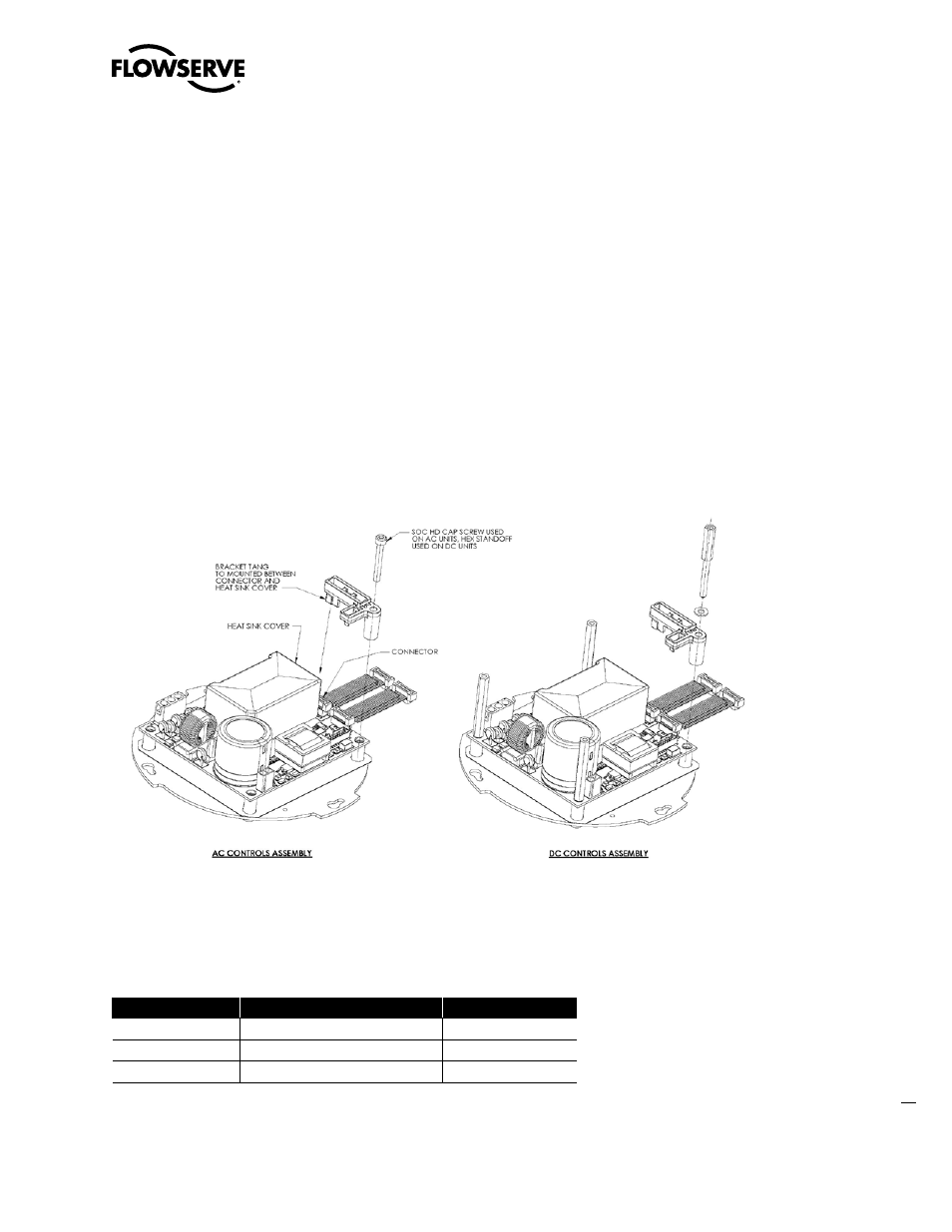
Connect wiring (See section 7 for wiring connection). Place retainer (#14-11 or 7) (Optional) on control module
ensuring the long tang sits in-between the Iram heat sink cover (#1-9 or 16) and connector on control module
For AC controls Insert screw (#14-12) in to retainer hole (#14-11) and tighten. For DC controls Insert flat washer (#1)
and standoff (#2) in to retainer hole (#14-11) and tighten. . (See Figure 6.9).
Figure 6.9 - Bracket Connector Retainer Assembly
6.4 Terminal Block
Table 6.9 Terminal Block Assembly
ITEM NUMBER
DESCRIPTION
QTY.
14-3
O'-RING
1
14-4
TERMINAL BLOCK SUBASSEMBLY
1
14-5
RETAINING RING
1