Foxconn 6627MA-RS2H User Manual
Page 20
Chapter 2 Installation Instructions
13
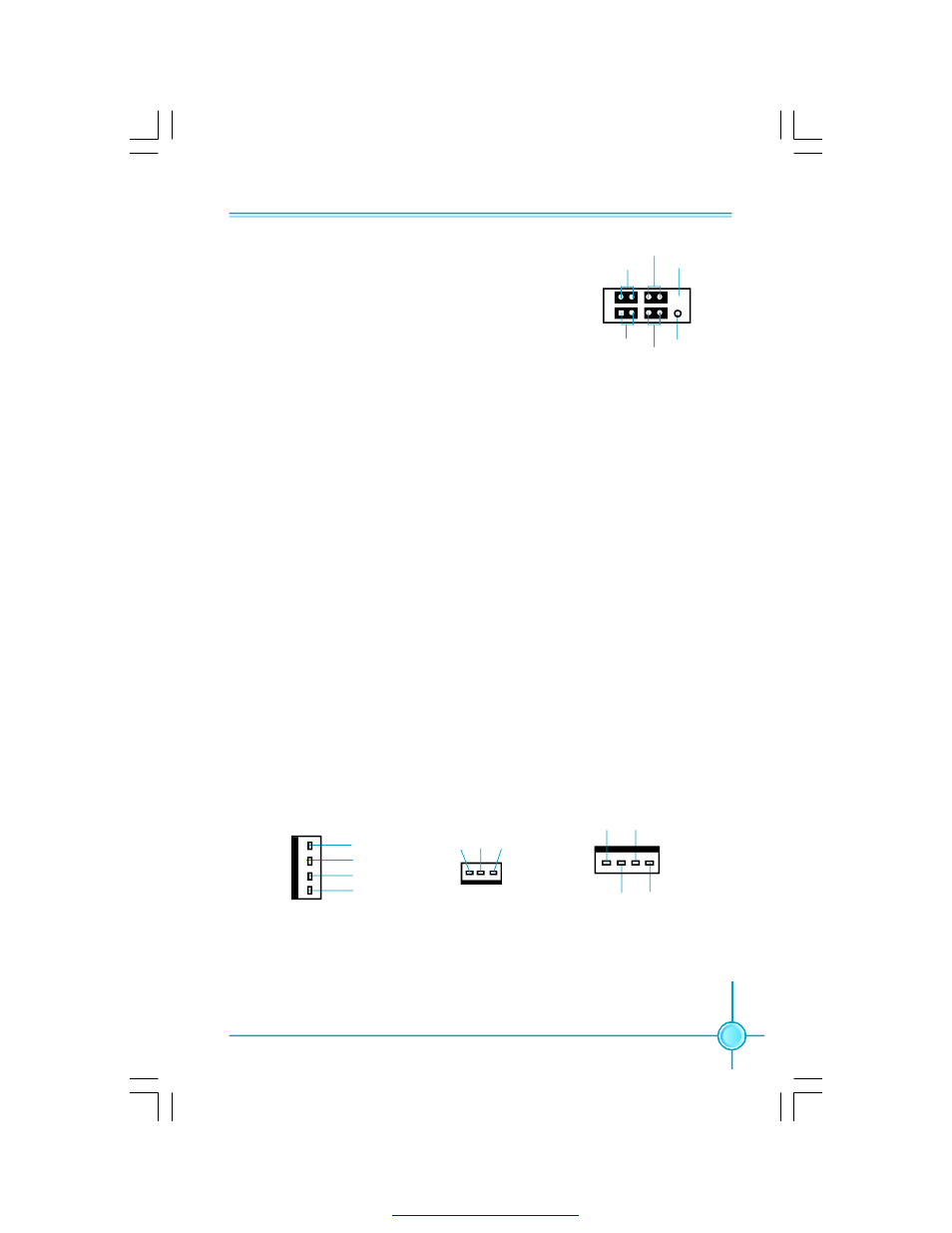
Front Panel Connector: FP1
This motherboard includes one connector for con-
necting the front panel switch and LED indicators.
HDD LED Connector (HDD-LED)
The connector connects to the case
’s HDD indicator LED indicating the activity
status of hard disks.
Reset Switch (RESET)
Attach the connector to the Reset switch on the front panel of the case; the
system will restart when the switch is pressed.
Power LED Connector (PW RLED)
Attach the connector to the power LED on the front panel of the case. The Power
LED indicates the system
’s status. When the system is in S0 status, the LED is
on. When the system is in S1 status, the LED is blink; W hen the system is in S3,
S4, S5 status, the LED is off.
Power Switch Connector (PWRSW)
Attach the connector to the power button of the case. Pushing this switch allows
the system to be turned on and off rather than using the power supply button.
+ -
+ -
1
FP1
NC
HDD-L ED
R E S E T
P W RL E D
P W R S W
E mpt y
Fan Connectors: CPU_FAN, SYS_FAN(optional), SYS_FAN_1(optional)
The fan speed can be detected and viewed in
“PC Health Status” section of the
CMOS Setup. These fans will be automatically turned off after the system enters
S3, S4 and S5 mode.
CPU_FAN
POWER
GND
1
CONTROL
SENSE
SYS_FAN_1
S E NS E
+1 2V
GND
1
SYS_FAN
SENSE
POW ER
GND
1
CONTROL
PDF 文件使用 "pdfFactory" 试用版本创建