4 part names and descriptions, 1 transmitter (hdc-th100), Part names and descriptions – IDK HDC-H100-C User Manual
Page 11: Transmitter (hdc-th100)
HDC-TH100-C/HDC-RH100-C User’s Guide
11
4 Part names and descriptions
4.1 Transmitter (HDC-TH100)
①
②
③
⑦
④
⑥
⑤
⑧
R
S
-232C
L
AN
Tx
Cat6 Tx for HDMI
POWER
LINK
HDCP
STATUS
POWER
LINK
HDCP
POWER
LINK
HDCP
STATUS
IN
P
UT
(MA
X
2
M)
O
UT
P
UT
F
G
D
C
5
V
2
A
DON'T
CONNECT
LAN
HDC-TH100-C
H
D
Ba
s
e
T
CAUTION
!
H
DM
I
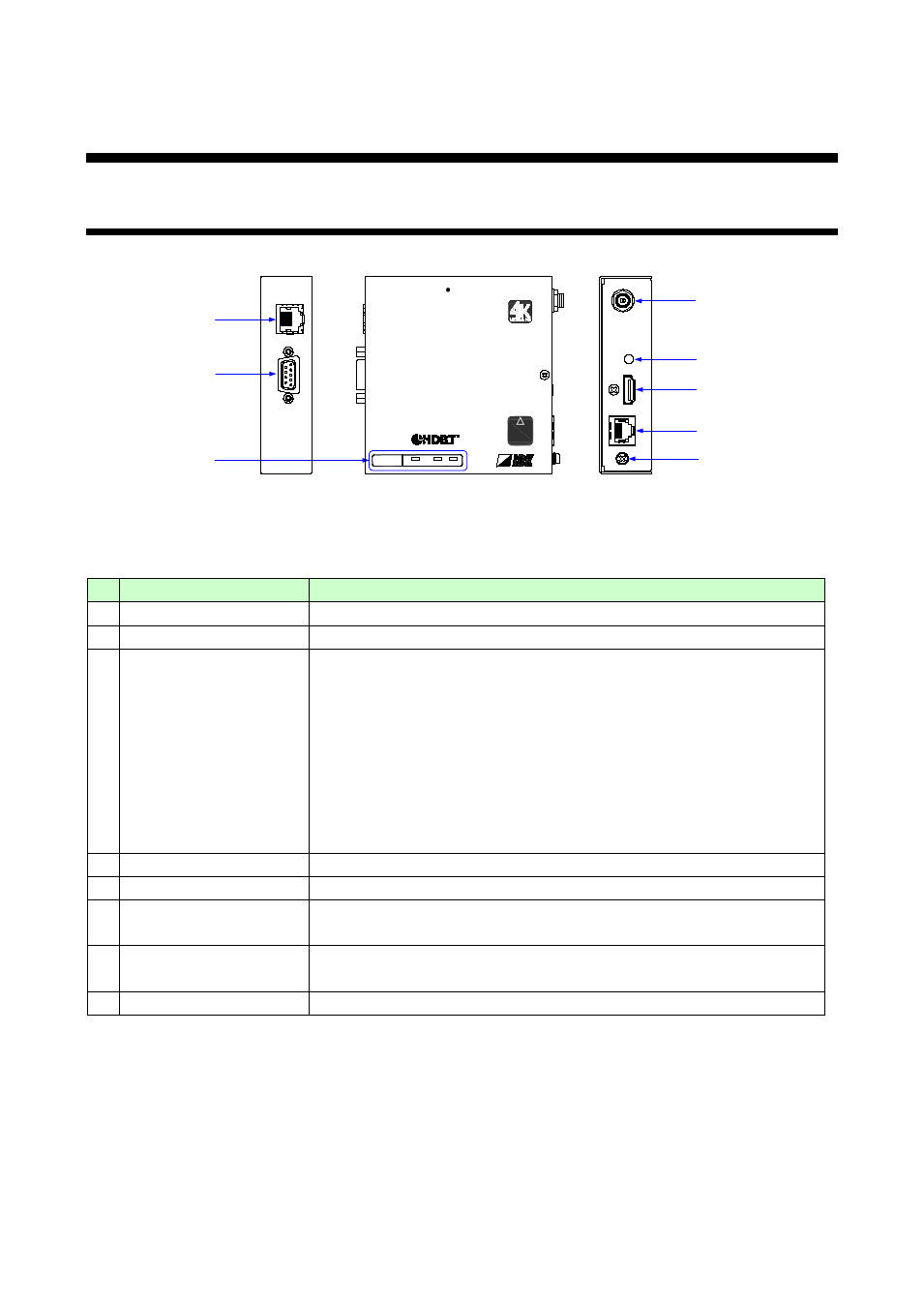
[Figure 4.1] Panel drawing (HDC-TH100)
[Table 4.1] Item descriptions (HDC-TH100)
#
Part name
Description
① LAN port
Port for LAN signals
② RS-232C port
Port for RS-232C signals
③ LED lights
POWER (Green): Lights when power is supplied from the AC adapter.
LINK (Orange): Lights when an HDC receiver is connected.
Blinks (0.5 second-interval) when the destination is in
standby state. LAN and RS-232C communications are
available.
Turns off when no connection.
HDCP (Yellow): Lights when there is an access to HDCP.
Blinks when there is no access to HDCP.
Turns off when no input signals are recognized.
④ AC adapter connector
Connector for the supplied AC adapter.
⑤ Cable fixing hole
Hole for the supplied cable clamp to secure the HDMI cable
⑥ HDMI input connector
Input connector for HDMI signals
Connect to source devices such as Blu-ray disk players.
⑦ Connector for long-haul
extension
Output connector for HDBaseT signals.
Connected to the receiver of the HDC series.
⑧ Frame ground
Ground terminal