ilve Built-in Cooktop User Manual
Page 19
Cut Out Dimensions for Built-in H / HF Series
Cut Out Dimensions for Built-in HP / XLP Series
Overall Dimensions for P Series Freestanding
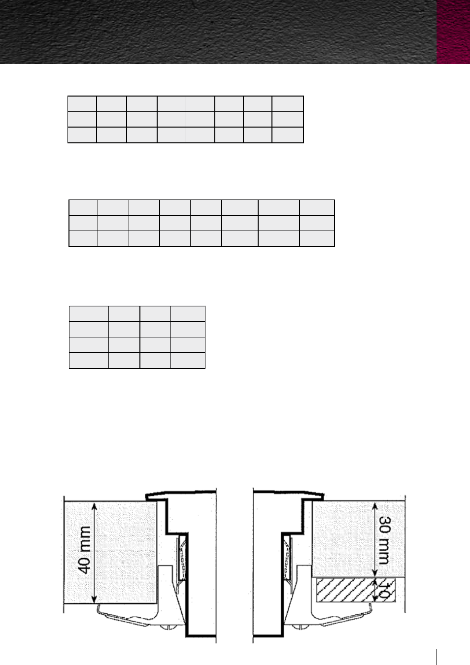
BUILT-IN INSTALLATION
To avoid liquid infiltrations under the working tops, it is necessary to apply a gasket which is supplied with
the top. The fixing to the furniture is carried out with clamps assembled on the appliance as per Figure 2.
For Freestanding cooking hob models (P665, P965, P1265) must be installed with the top of the hob level
with the bench and must support a minimum weight of 100 kg.
Mod
P665 P965 P1265
A
600
900
1200
B
650
650
650
Height
85
85
85
Mod H30 H360 H60 H70 H38 H39 HF40
A
270
555
555 555 755 835
360
B
475
475
475 475 475 475
490
Mod HP45 HP65 HP95 HP75 HP125 HP1230 XLP90
A
380
570
850
680
1130
1120
875
B
481
485
485
490
480
300
570
Figure 2
Buil
t-in cooktops
19
ILVE Built-in Cooktop Operating & Installation Manual