ilve Built-in Cooktop User Manual
Page 25
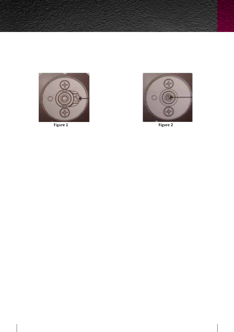
Minimum flow of cooking hob taps (Figure 1)
• Switch on the burner and turn the control knob towards the minimum flow position;
• Remove the knob;
• Using a screwdriver, adjust the internal screw until the correct low flame is obtained, the screw is
located just to the right of the shaft see figure 1
• Refit the knob.
Minimum flow of non-valved cooking hob taps (Figure 2)
• Switch on the burner and turn the control knob towards the minimum flow position;
• Remove the knob;
• Insert a small screwdriver into the shaft of the gas valve and adjust the internal screw until the
correct low flame is obtained; see figure 2
• Refit the knob.
• Unscrew the adjustment screw to increase the flow, or tighten it to reduce the flow.
• The adjustment is correct when the low flame measures approximately 3 or 4 mm.
• For ULPG the adjustment screw should be tightened all the way.
• When changing quickly from maximum to minimum flow and vice versa make sure that the flame
does not go out.
ENSURE THE MINIMUM FLAME WILL NOT BE EXTINGUISHED BY AIR DRAUGHTS
Check that the igniter for each burner successfully ignites the gas and that the burner remains
alight. If an igniter fails to work or a burner fails to remain alight, first remove the plug from the
electrical power outlet, and then check that all electrical connections are in place. If the hotplate fails
to operate correctly, contact Eurolinx Pty Ltd or their appointed agent for service. When satisfied that
the hotplate is operating correctly, instruct the customer in its safe operation. Ensure the customer
understands fully by having them operate the hotplate in all its functions.
Buil
t-in cooktops
25
ILVE Operating Manual