Insinger GalleyMaster Series User Manual
Page 15
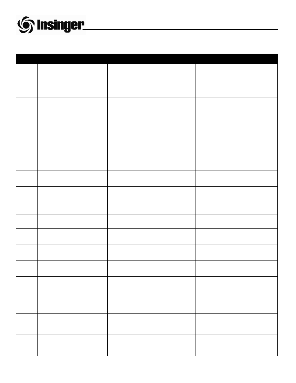
CONTROLS AND INDICATORS (STEAM HEATED MACHINES)
ITEM #
CONTROL
TYPE
FUNCTION
1
Control power switch.
Off-On selector switch on control panel.
Controls 24 vac power to control
circuit.
2
Control power light.
Yellow pilot light on control panel.
Signals control power state.
3
Start switch.
Green pushbutton on control panel.
Starts pumps and conveyor(s).
4
Stop switch.
Red pushbutton on control panel.
Stops pumps and conveyor(s).
5
Wash tank heat indicator.
Yellow pilot light on control panel.
Signals steam coil energized in wash
tank.
6
Rinse tank heat indicator.
Yellow pilot light on control panel.
Signals steam coil energized in rinse
tank.
7
Final rinse heat indicator.
Yellow pilot light on control panel.
Signals booster steam flow ener-
gized.
8
Check conveyor indicator.
Red pilot light on control panel.
Signals conveyor jam.
9
5 amp circuit breaker.
White circuit breaker on control panel.
Over-current protection for control
circuit.
10
Water and steam ball valves.
Valve located on respective piping
string.
Opens or closes incoming steam or
water line.
11
Damper blade position control.
Handle (90° rotation) at vent duct
connections.
Regulates vent duct exhaust flow.
12
Wash tank water level sight
glass.
Porthole located on front of wash tank.
Indicates level of water in wash tank.
13
Rinse tank water level sight
glass.
Porthole located on front of rinse tank.
Indicates level of water in rinse tank.
14
Thermometers - wash and
rinse.
Dial gauges located on front of wash
and rinse tanks.
Indicate water temperature in wash
and rinse tanks.
15
Thermometer - final rinse.
Dial gauge located on top of final rinse
piping.
Indicates final rinse temperature.
16
Pressure gauge - final rinse.
Dial gauge located on top of final rinse
piping.
Indicates final rinse pressure.
17
Temperature control -
wash and rinse.
Round slotted adjustment knob located
on the wash or rinse tank temperature
control board in the control panel.
Regulates temperature of the wash
and rinse tank water.
18
Low water level switch.
Float switch located in wash and rinse
tanks.
Disables respective tank steam coil.
19
Final rinse temperature control.
Left slotted adjustment screw inside the
round dual thermostat on front of steam
booster.
Controls temperature of final rinse
water.
20
Final rinse low temperature
cutoff switch.
Right slotted adjustment screw inside
the round dual thermostat on front of
steam booster.
Disables pumps and conveyor(s)
when water is below 180° F.
PART 1 TECHNICAL INFORMATION