Interlink Electronics VersaPad USB User Manual
Page 11
USB VersaPad®
Integration Guide
www.interlinkelectronics.com
9
5.1.4 PCB Support
The clamping parts used to secure the PCB component side of the VersaPad module
should provide additional support wherever it is allowable.
5.1.5 Enclosure
Material
Bezels and encasements can be made of conductive or non-conductive materials.
Proper care should be taken to avoid creating ESD concerns
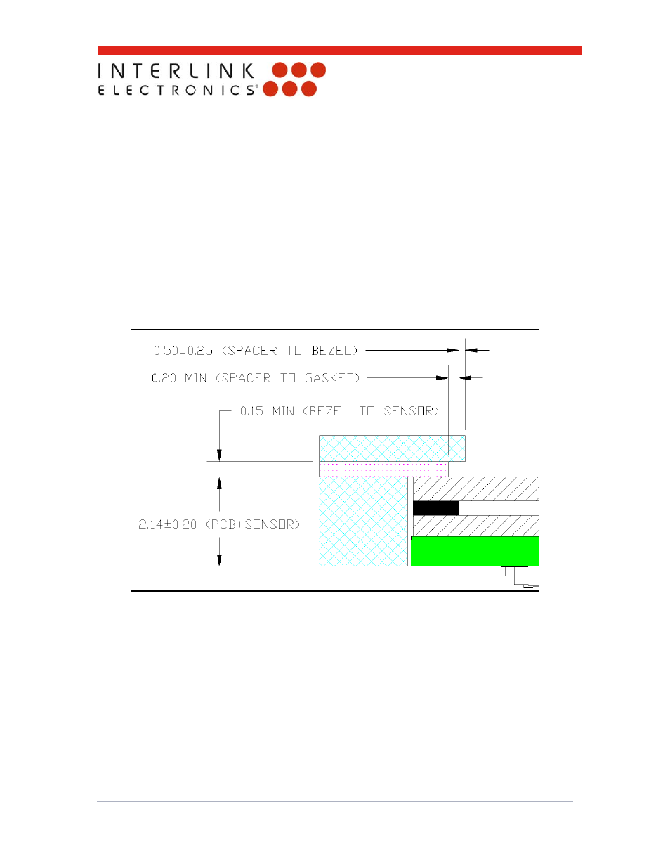
5.1.6 Critical Capture Dimensions
The figure below shows the critical dimensions in positioning of the bezel or top case,
gasket, VersaPad, and enclosure. These recommendations are chosen to prevent
embossing near the spacer and to prevent inadvertent pressure on the top surface of
the sensor. All dimensions and tolerances apply to both top and bottom mounting
methods.
Figure 5: Critical capture dimensions. Drawing is not to scale.