0 mounting – Interlink Electronics VersaPad USB User Manual
Page 8
USB VersaPad®
Integration Guide
www.interlinkelectronics.com
6
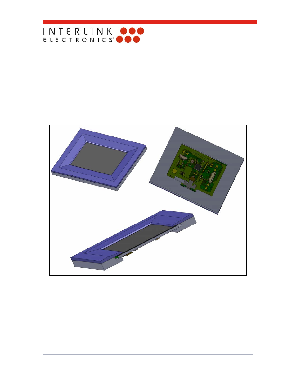
5.0 Mounting
A general bezel mounting method as shown in figure 3 is one possible way to mount the
VersaPad Module. Mechanical installation of the VersaPad module has many critical features
that must be considered for mounting. In particular, care should be taken to avoid inadvertent
pressure on the top membrane of the sensor as such pressure could be confused with a user’s
external touch. The membrane is supported at its edge by an internal spacer, shown in figure 4
as the dashed line. Parts used to capture the VersaPad module must not make contact with the
sensor inside the electrically active area. A general 3D CAD model of Interlink’s suggested
mounting method and geometry can be found on our website at
www.interlinkelectronics.com/Support
.
Figure 3: VersaPad Module Bezel Mounting Concept