5 molex connector pin-out – Interlink Electronics VersaPad USB User Manual
Page 15
Advertising
USB VersaPad®
Integration Guide
www.interlinkelectronics.com
13
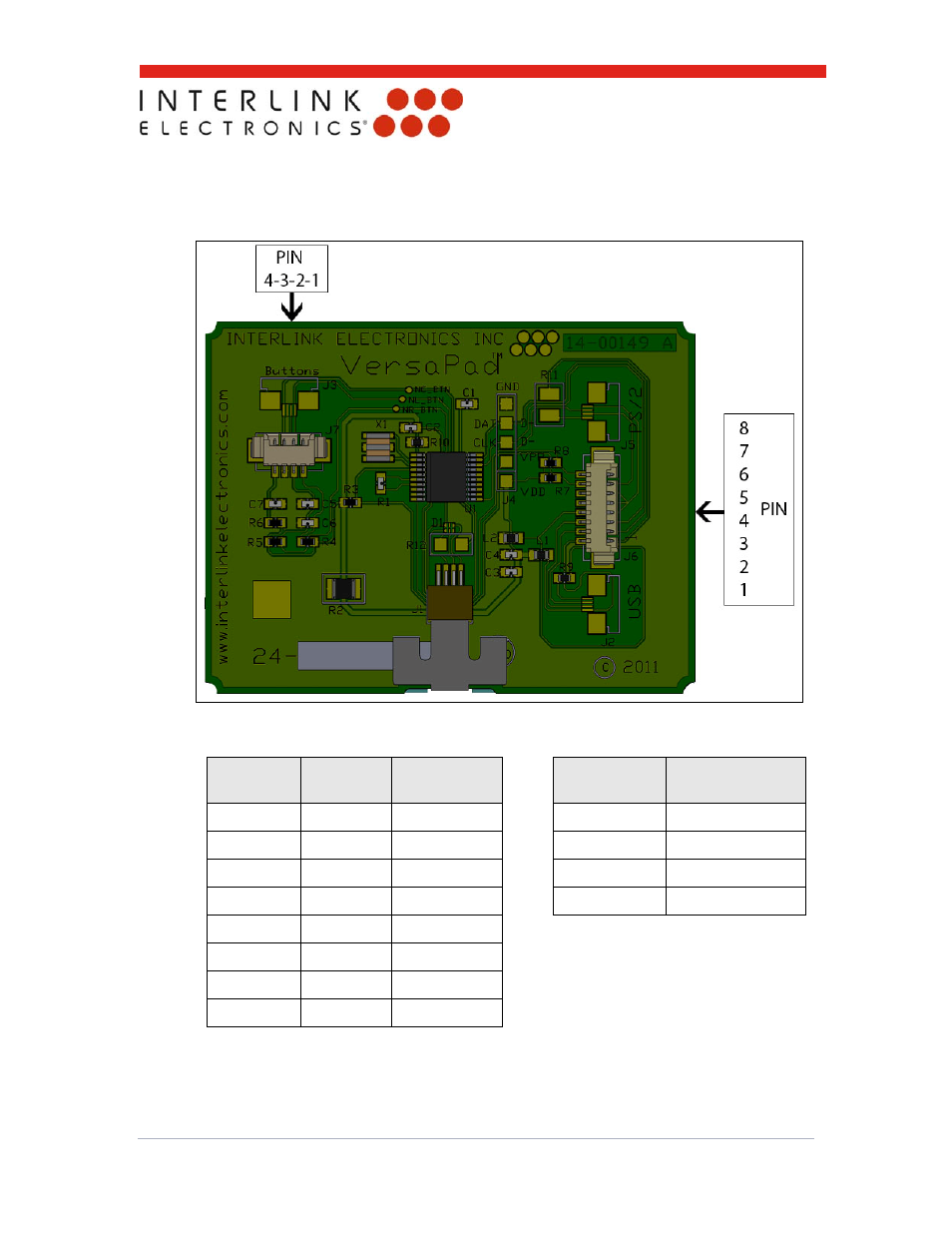
6.5 Molex Connector Pin-out
The following figure and table shows the pin-out for Molex header connections to the
J6 and J7 headers.
Figure 9: Molex Header Pin-Outs
J6 Pin
Signal
Signal
Description
J7 Pin
Signal
1 VCC +5
V
1
Left
Button
2 D+ D+ 2 Right
Button
3 D- D- 3
Ground
4 GND
Ground
4 Center
Button
5 GND
Ground
6 GND
Ground
7 NC --
8 NC --
Table 1: J6 & J7 Molex Header Pin-Outs
Advertising