Section 3-3-2: venting components, Installation – Montigo H38DF-CLCR User Manual
Page 17
Page 17
XG0213 - 150204.2
H*38DF-CLCR Corner Gas Fireplace
Installation
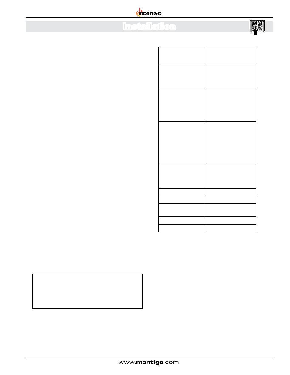
A - Termination
PTO4 (3" Length)
PTO4F (3" Length)
PVTKK1SS
B - Frame Kits
MSR (Stucco Frame)
MOSR (Stucco Frame)
BSR-4 (4" Brick Frame)
BSR-6 (6" Brick Frame)
C - Flex Sections
PFL - 1 (12" f/f Section)
PFL - 18 (18" f/f Section)
PFL - 2 (24" f/f Section)
PFL - 3 (36" f/f Section)
PFL - 4 (48" f/f Section)
PFL - 6 (72" f/f Section)
D - Rigid Sections
PXT - 5 (5" f/f Section)
PXT - 10 (10" f/f Section)
PXT - 20 (20" f/f Section)
PEXT - 1 (12" f/m Section)
PEXT - 2 (24" f/m Section)
PEXT - 3 (36" f/m Section)
PEXT - 4 (48" f/m Section)
PEXT - 6 (72" f/m Section)
E - Elbows
PEL-90MM (m/m 90º Elbow)
PEL-90FF ( f/f 90º Elbow)
PEL-90FM ( f/m 90º Elbow)
PEL-45FM ( f/m 45º Elbow)
F - Support Ring & Plate
PSPXT-8
G - Firestop
FS-8
H - Roof Flashing
PRF-7 (1/12 - 7/12 pt�)
PRF-12 (7/12 - 12/12 pt�)
I - Heat Shield
RHS103
J - Heat Guard
MTKOG
Connection and installation of the vent components should
adhere to the following guidelines:
Section 3-3-2: Venting Components
The following components and associated Montigo part num-
bers are available for installation of a Wall Mounted Termination�
Use only Montigo Vent Components� Use of non-Montigo parts
will void the warranty and may impede operation of the fireplace.
IMPORTANT:
Please Refer to your Building Envelope Engineer
or Waterproofing Consultant for a review of ALL
penetrations through exterior walls or the roof�
Montigo recommends the use of a flex section for the final pipe
connected directly to the fireplace offering greater flexibility of
installation and absorption of movement.
Firestops must be installed as required by National & local codes
.
Montigo recommends that all exterior corners and joints be sealed
with exterior caulking. However, we encourage you to consult
your Building Envelope Engineer or Waterproofing Consultant
for further recommendations.
Use any combination of rigid and flex pipe as required and in
any orientation (Male connectors can face in any direction).
Flex sections may be stretched up to 50% of their total length
(e.g. a 24” section maybe stretched to 36”).
Connect all vent sections using a minimum of three sheet metal
screws on the outer pipe flue.
Ensure the pipe ends male to female slide in a minimum of 1
1/2” of overlap.
Ensure all horizontal runs are supported with a minimum of 3
supports per 10’ of venting.
When hanging/ supporting venting, ensure that 1” clearance
is maintained on sides and bottom of vent runs and 2” above
horizontal vent runs to any combustible material.
Rigid pipe may be cut less than half way from the female end only�
Ensure when cutting sections of rigid pipe to maintain integrity
of internal supports.
Place the springs, supplied with the pipe kit, between the outer
and inner pipes to keep the pipes separate and avoid any
possible hot spots.