Installation, Features – Montigo RX82 User Manual
Page 6
6
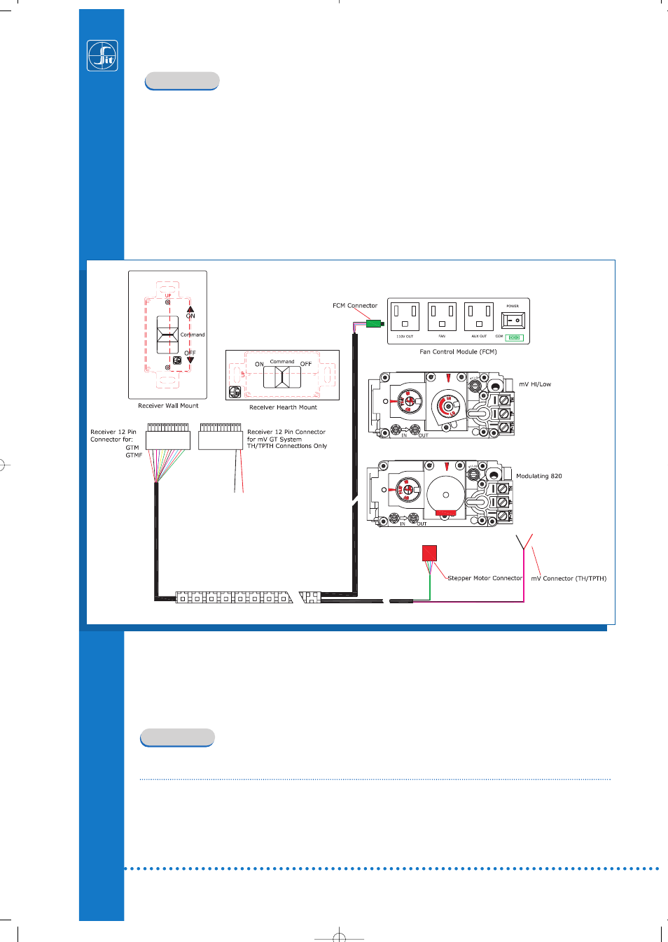
Fig. 5: Wiring diagram.
INSTALLATION
The PROFLAME System is designed to command uniquely the 820 NOVA millivolt Combination
Gas Control, the 820 NOVA mV converted with the STEP MOTOR modulating kit or the 829 mV.
The wiring diagram of all the electrical connections is shown in Fig. 5.
Particularly shown are three main elements of the system.
The Fan Control Module, Receiver an 820 and 829 Nova mV Gas Valve can all be connected by sin-
gle wire harness.
The FCM provides for a constant 120V outlet, Fan speed control and constantly powered 120V
Auxiliary outlet.
FEATURES
FUNCTIONALITY OF THE RECEIVER
The Receiver is supplied by four (4) AA batteries. The receiver accepts commands via radio signal
sent from the transmitter. The receiver sends commands by the wire harness to the various com-
ponents of the system. When the system is turned on the Receiver performs a calibration of the
stepper motor after which an acoustic signal (“beep”) is generated to indicate the Receiver is
ready to receive commands from the Remote Control.