Installation, Installing the vertical linear power vent, Installing the horizontal linear power vent – Montigo LDVPV47 User Manual
Page 8
Page 8
LDVPV47 Linear Power Vent System
XG0750 - 112911
Installation
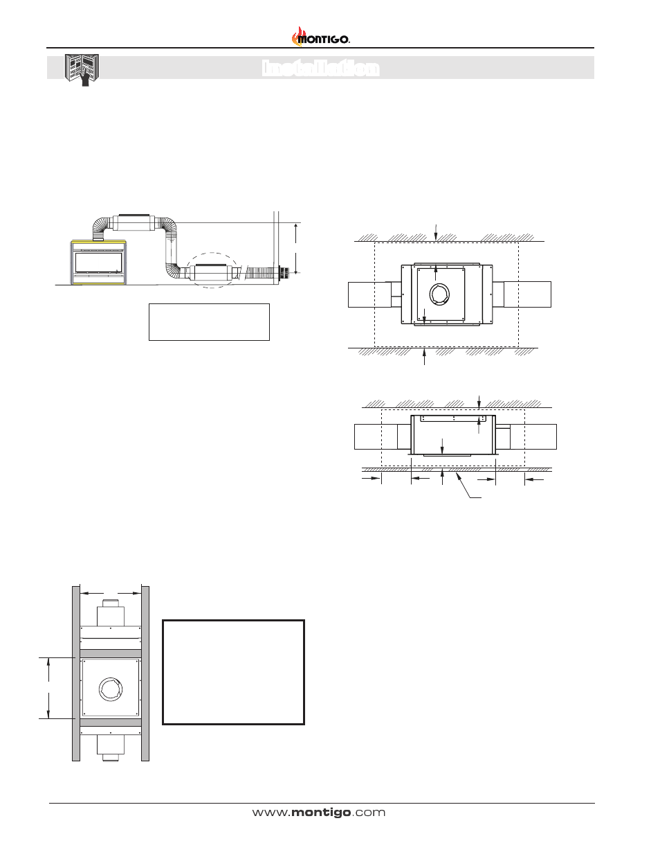
Figure 5a. HorizontaI Linear Power Vent with Horizontal Vent Run.
(Optional installation location shown).
Linear Power Vent - Horizontal / Downward Vent
Multi-elbow installations are possible up to a maximum eighty feet
(80'-0"), with three (3) 90° elbows. Minimum vent run from Fireplace
to Power Vent must be two feet, (2'-0"). Maximum allowable vent run
must be reduced by Ten feet (10'-0") for every Additional elbow added.
Deduct ten feet (10'-0") of vent length for every Additional one foot (1'-0")
of vent run traveling in a downward direction.
Horizontal Installed
Linear Power Vent
Horizontal Run Flex Pipe
Vertical
Flex Pipe
90deg
Elbow
90deg
Elbow
Termination
Important:
Maximum Vent Run not to exceed
Eighty feet (80’-0”) feet.
Optional location
of Horizontal mounted
Linear Power Vent
6’-0”
Selecting A Termination Location
Please consult Appendix I, to ensure that the location of the vent run
termination is within the guidelines.
Installing the Vertical Linear Power Vent
1. The linear power vent can be installed to existing stud construction
or directly to cement wall or roof. The LDVPV must maintain 1"
clearances to combustibles. The required service access panel
must be framed at 18" X 18". To enclose the service access
panel, (at less than 1") a minimum 30% free air must be supplied
at all times.
2. Plug the power chord into the available slot in the linear power vent.
3. Secure all venting joints with at least three self-tapping screws.
Figure 6. LDVPV47 Linear Power Vent, Vertical framing dimensions.
18
18
Note:
The required service access
panel must be framed at 18"
X 18". To enclose the service
access panel , (at less than 1")
a minimum 30% free air must
be supplied at all times.
Installing the Horizontal Linear Power Vent
1. The linear power vent can be installed to existing stud construction
or directly to cement wall or roof. The LDVPV must maintain the
clearance to combustibles shown in Figure, 4a. The required
service access panel must be framed at 18" X 18". To enclose
the service access panel, (at less than 1") a minimum 30% free
air must be supplied at all times.
2. Plug the power chord into the available slot in the linear power vent.
3. Secure all venting joints with at least three self-tapping screws.
Top View
Side View
Figure 6a. LDVPV47 Linear Power Vent, Horizontal framing dimensions.
1”
Clearance
10”
Clearance
2”
Clearance
Combustible Drywall ceiling,
with access panel
10”
Clearance
Combustible Materials
3”
Clearance
3”
Clearance
Combustible Materials
Combustible Materials