Installation, Top vent venting runs, Installation of top vent dv – Montigo MD44 DV User Manual
Page 6
Part No. XG0120
Page 6
MD44-DV Direct Vent Vented Fireplace
Installation
Top Vent Venting Runs
Before you install any venting, you must determine whether the
venting run will be acceptable. Unacceptable venting can affect the
fireplace's combustion.
n
the maximum horizontal vent run for a Top Vented unit is 20 feet
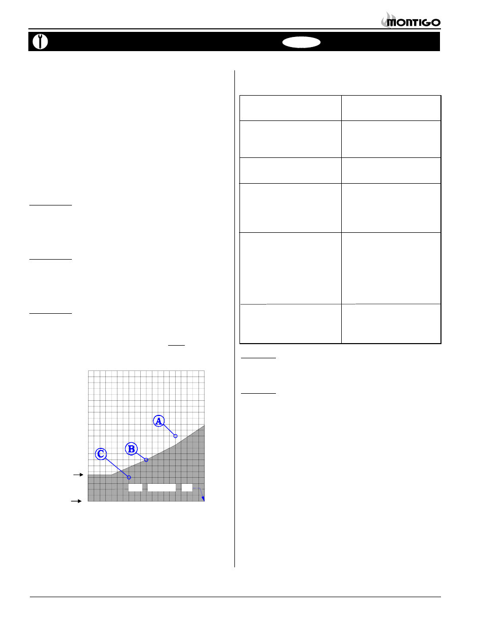
The Venting Graph
Measure the vertical height from the fireplace hearth to the centre of
the termination and the horizontal run from the from the fireplace flue
collar to the wall flange of the termination. Plot on the Venting Graph
(Fig. 9) with an 'X'.
If the 'X' falls on or above the top boundary of the shaded area, the
installation is acceptable.
Example A: (Acceptable Installation)
If the vertical dimension from the floor of the fireplace
is 11 ft. and the horizontal run to the wall flange of
the vent termination is 15 ft., this would be an
acceptable installation.
Example B: (Acceptable Installation)
If the vertical dimension from the floor of the fireplace
is 7 ft. and the horizontal run to the wall flange of the
vent termination is 10 ft., this would be an acceptable
installation.
Example C: (Unacceptable Installation)
If the vertical dimension from the floor of the fireplace
is 4 ft. and the horizontal run to the wall flange of the
vent termination is 7 ft., this would NOT be an
acceptable installation.
Figure 7.
Venting Graph
Center of
Vent Pipe
Hearth
Horizontal Run (feet)
Vertical
Height (feet)
Max. Horizontal Run
0
5
10
15
20
0
5
10
15
20
Example:
For our shortest venting configuration use components A
and F (see Figure 8).
Example:
A 10' section and elbow (PIHR-10) used in conjunction
with 3 ft. flex section (PFL-3) will, when extended in a five
foot chase, allow for a maximum horizontal run of twelve
and one-half feet from the centre of the fireplace to
outside wall and a minimum of 7'6" when retracted in
opposite direction (see Figure 10 and 11).
"D" flex sections and "E" solid sections may be used in
conjunction with one another to obtain different possible
horizontal length installations. NOTE: Flex section must
not exceed maximum horizontal length of 3 feet. (see
Figure 12).
Installation Of Top Vent DV
The following venting components are available for the MD44-DV
Top Vent:
A - Termination
PTO-3 (3" length)
PTO-3F (3" length)
B - Termination Frames
MSR (stucco frame)
MOSR (stucco can)
BSR (brick can)
C - Solid section & elbow
PIHR-6 (72" length)
PIHR-10 (120" length)
D - Flex sections
PFL-1 (12" section)
PFL-2 (24" section)
PFL-3 (36" section)
PFL-4 (48" section)
E - Solid sections
PXT-18 (18" f/f section)
PEXT-1 (12" m/f section)
PEXT-2 (24" m/f section)
PEXT-3 (36" m/f section)
PEXT-4 (48" m/f section)
PEXT-6 (72" m/f section)
F - Elbows
PEL-90M (m/m 90° elbow)
PEL-90F (f/f 90° elbow)
PEL-90FM (f/m 90° elbow)
Top Vent