10 appendix, 1 wiring diagram nortec me control, Wiring diagram nortec me control – Nortec ME Control User Manual
Page 74: 74 appendix, Control unit
74 Appendix
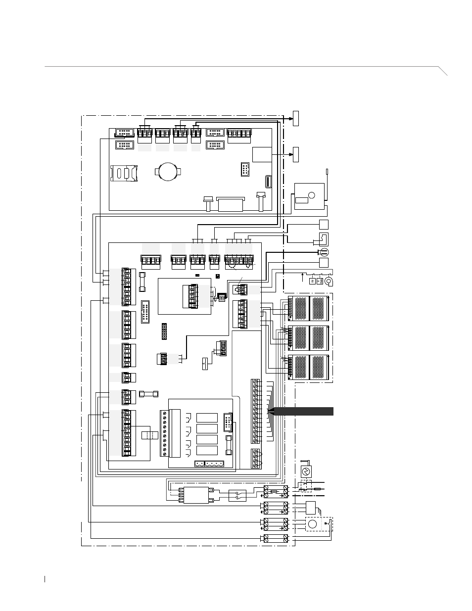
10 Appendix
10.1 Wiring diagram Nortec ME Control
A1
Driver board
A2
Control board
B1
Ventilation interlock
B2
Max. humidity monitor
B3
Air flow monitor
B4
Temperature and conductivity measuring
B5
Sensor temperature and conductivity measuring
B6
Level sensor dosing pump (option)
B7
Demand or humidity/temperature signal
B8
External On/Of
f switch (external enable)
B9
Air temperature monitoring duct (option)
B
AT
Backup battery (CR2032, 3V)
CS
Current sensor (UV lamp)
D.L
VL
Terminal level switch dosing liquid tank
D.PUMP
Terminal dosing pump
F1
Fuse mains supply (1
A slow acting)
F2
Fuse 10/24 VDC supply(630 mA
slow acting)
F3
Internal fuse mains supply (6.3
A fast acting)
F4
External fuse mains supply (10
A slow acting)
H1
Remote operating and fault indication board (option)
J1
Cable bridge if no external On/Of
f switch is
connected
J2
Cable bridge demand signal
(for commisioning only)
J3
Cable bridge if no safety chain is connected
JP4
Jumper fitted= 24 V on X16 (JP5 removed)
JP5
Jumper fitted= = 10 V on X16 (JP4 removed)
JP/TR
Jumper fitted on the last driver board
K1
External safety chain
K2
Cable harness from hydraulic module
LS1
Leakage monitoring board (option)
LS2
Sensor leakage monitoring (option)
M1
Dosing pump (option)
NF
Mains filter
Q
Electrical isolator
S1
Humidification On/Of
f switch
S3
On/Of
f switch control unit
SD
Memory card
SUPPL
Y
Terminal mains supply voltage
SF
Snap feritte
(wrap cable 3 times through ferrite)
T1..T3
24V power supply (T3 for systems with 4 or 5 stages only )
UV
UV lamp (option)
U.V
.
Terminal UV lamp
X4
Terminal cable harness hydraulic module
PMC-24V100W1AA
PMC-24V100W1AA
Ethernet
3V
CR2032
X1
X2
SF
USB
J1
RJ45
BAT
SD
X3
X4
X19
S1
X7
CS
F1
(1 AT)
F2
(630 mAT)
X9
X8
X10
X20
X11
X12
X13
X14
X15.1
X15.2
X16
T3
T1
T2
B5
J6
J10
J12
J14
J2
24V IC
GND
H1
B4
Error
1
2
3
Service
4
5
6
Running
7
8
Unit On
9
10
JP5: 10V
JP4: 24V
JP/TR
B3
K1
K2
B2
B1
PMC-24V100W1AA
B8
RS485
UV
N
L
N
L1
N
L1
PE
N
L
PE
PE
UV–
UV+
PE
PMP N
PMP L
PE
DOSP–
DOSP+
PE
N/GND
L/24V P
AIRT+
SHIELD
AIRT–
GND
24V P
24/10 V TMP
GND
HUM
24V E Enable
D–
GND
D+
D–
GND
D+
24V E
GND
GND
24V E
24V E
24V E
24V E
24V E
LEAK
CS1
LVL DP
GND
FQ+
24V P
N FQ2
N FQ1
ERR FQ
GND
24V P
5V P
GND
PS4
PS5
24V 3
GND
GND
GND
24V 1
24V 2
SC2
SC1
24V SCB
GND
24V P
24V P
24V SCA
Y2
Y1
Y10
Y9
Y8
Y7
Y6
Y5
24V P
Y11
Y4
Y3
PS1
PS2
PS3
LEVEL/T
GND
24V P
Y
B7
A2
A1
GND
+
–
GND
+
–
GND
+
–
GND
24V+
X5
NF
S3
L
N
1
2
L
N
L
N
PE
L
100...240 V/1~/50..60 Hz
N
F4
Q
M1
B6
M
1
2
3
4
5
6
7
8
9
10
11
12
13
14
1
2
3
4
5
6
7
8
9
10
11
12
13
14
A
A
B
B
min. °C
B9
J2
J3
X4
F3
D.PUMP
U.V.
SUPPLY
D.LVL
Tmp bk
Cnd bn
Cnd wh
Tmp bu
Shield
LS1
LS2
Control unit