6 mechanical mounting, 7 post-installation checks – Northern Airborne Technology NPX138 User Manual
Page 21
NPX138 Panel Mount Radio Manual
SM41 Rev. 4.00
2.3.6
Mechanical Mounting
Installation of the transceiver should be in accordance with the original aircraft
manufacturer’s instructions for continued airworthiness or AC 43.13-1B Change 1,
chapter 7, sections 2 to 7 and AC 43.13-2A, chapter 2. Pr 35 Dzus rail or equivalent may
be used.
Mounting the NPX138 requires a Dzus rail assembly with an opening width of 127 mm
(5 inches) and a front clearance width of 146.1 mm (5.75 inches). Height requirement is
47.6 mm (1.875 inches). Refer to the mounting drawings and unit mechanical
specifications to determine proper clearance dimensions. Be sure that adequate
clearance is allowed for the cable connections to each unit.
2.3.7
Post-Installation Checks
2.3.7.1
Voltage/resistance checks
Do not attach the NPX138 until the following conditions are met.
Check the following:
a) P101
pins
<12> and <13> for +28 Vdc relative to ground.
b) P101
pins
<22>, <23>, <24> and <25> for continuity to ground (below 0.5
Ω).
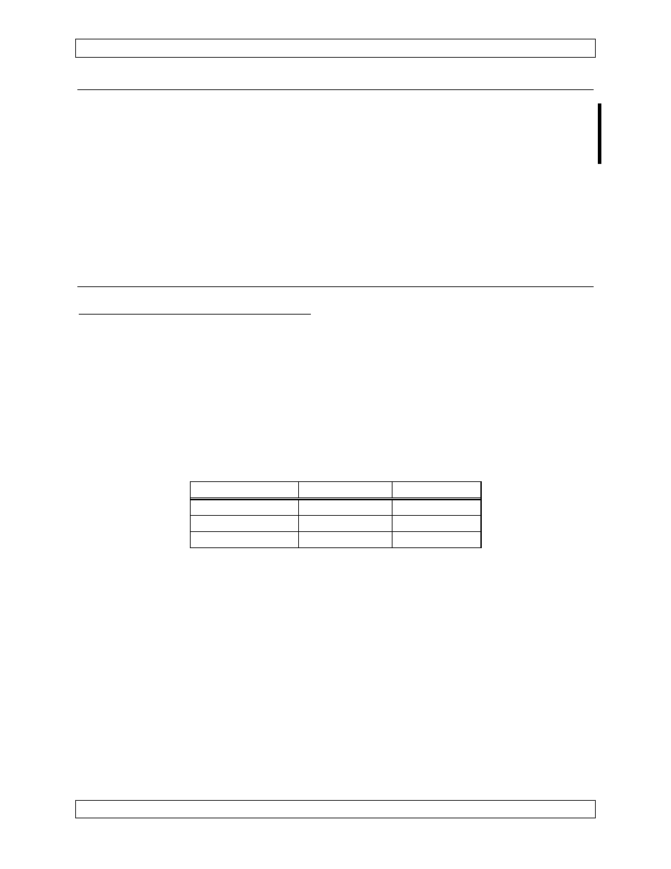
c)
Light voltage as per table below.
P101 Pin #
Voltage
28 Volt Models
11
28 Vdc
14 Volt Models
10
14 Vdc
5 Volt Models
10
5 Vdc
Light Voltage
Ensure that the antenna is disconnected for the following test or erroneous
readings may be obtained
d)
Radio coax connector for continuity to the antenna coax connector (shield and
center conductor), and for open circuit from the center conductor to ground and
open circuit from the center conductor to the shield.
Page 2-4
Nov 10, 2003
ENG-FORM: 805-0104.DOT
Amendment # 5
Jan 14, 2008
PROPRIETARY AND CONFIDENTIAL TO NORTHERN AIRBORNE TECHNOLOGY LTD.