2 initial operating display, 3 display – Northern Airborne Technology NPX138 User Manual
Page 36
NPX138 Panel Mount Radio Manual
SM41 Rev. 4.00
3.2.2
Initial Operating Display
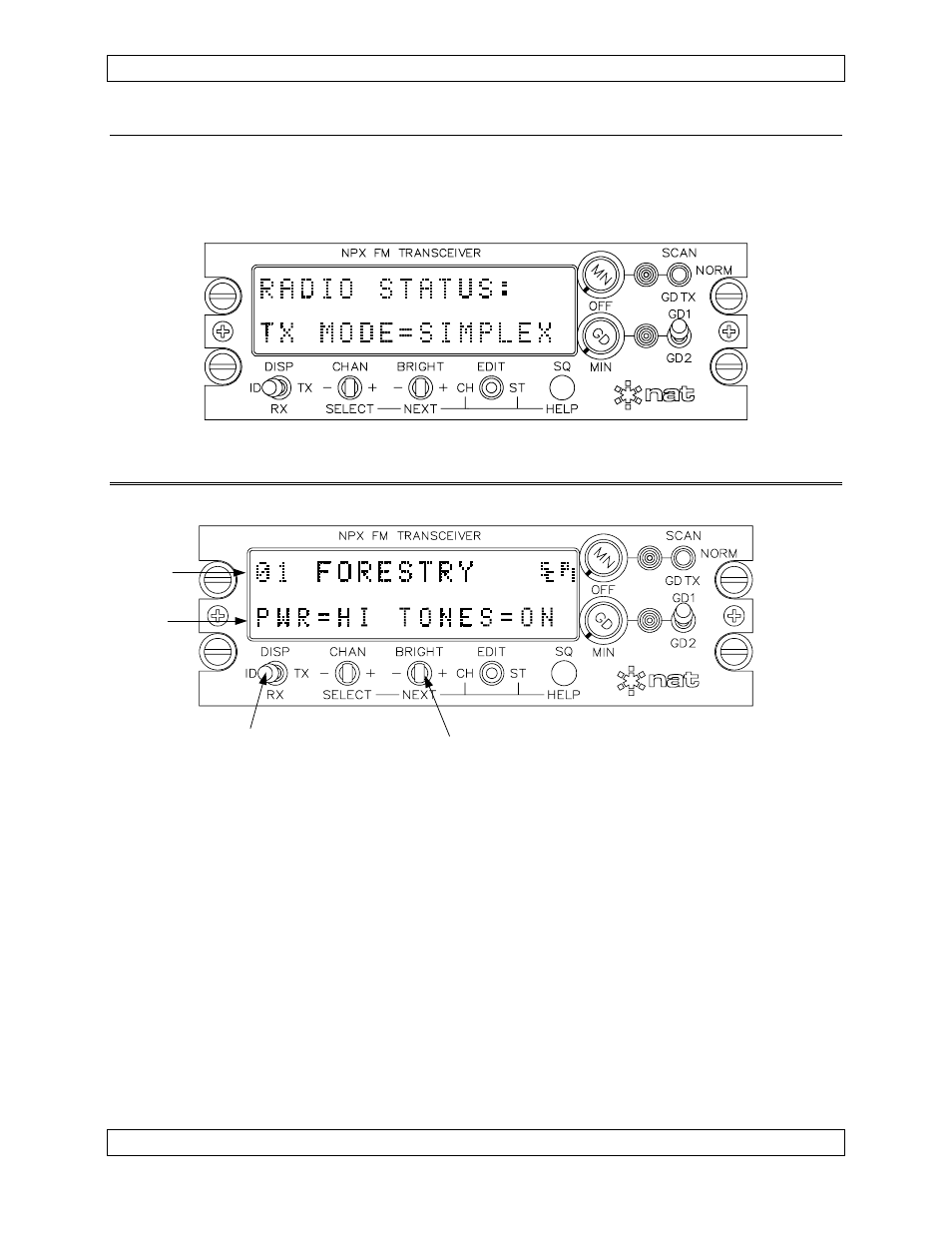
If you decline ‘Help’ (by using the NEXT switch as directed), the radio will display a
summary of the installed functions and current settings (this feature can be disabled at
installation for faster start-up). The radio is then ready for normal operation.
3.3
Display
Channel
Info
Status
Info
Brightness Control
Channel Display Mode
The diagram above shows a typical radio display in ‘Normal’ operating mode. The upper
row of the display contains information related to the currently selected channel. The
specific information displayed depends on the setting of the DISPLAY switch located in
the bottom left hand corner of the front panel. When it is in the ID position (as shown
above), the display shows the channel identifier or name. When it is in the RX or TX
position, the display shows the respective receive or transmit information. See section
3.6 for further details on the Channel Display.
The lower row of the display contains information related to specific radio functions.
Normally, it shows the settings for the power level and the CTCSS tones. However,
entering the Status edit mode allows the display of other function settings. See section
3.8 for further details on displaying and changing Status information.
The BRIGHT switch controls the brightness of the display text. See section 3.5.2 for
further details.
Page 3-2
Nov 10, 2003
ENG-FORM: 806-0105.DOT
CONFIDENTIAL AND PROPRIETARY TO NORTHERN AIRBORNE TECHNOLOGY LTD.