Power supply and fan modules – Olson Technology MUSCLE-EM55X User Manual
Page 21
OTOT-EM55X/XL Optical Transmitter Rev. x1
www.olsontech.com
20
2, 3
optical fibre outputs (optional located on front panel)
4
Not used in OTOT-EM55X, cover
5
I/O ports
6
RS485 interface (RJ-45 female): a-versions: master; b-versions: slave
7
RS232 interface (SUB-D9 male)
8
a-versions: Ethernet interface; b-versions: RS485 slave interface (RJ-45 female)
9
2 green LED’s Ethernet link & data (a-versions only)
10, 11
power supply + fan modules (field replaceable)
Power Supply and Fan Modules
There are two different types of power supply and fan modules available for the OTOT-EM55X and OTOT-EM55XL.
All of them can be either mounted on the left hand or right hand side. It is possible to replace or exchange all of the
modules during operation. This offers a big flexibility to the end user in order to customise the OTOT-EM55X/XL ex-
actly to the actual needs.
The necessary outlets for the power supply modules have to be directly located in the rear of the device and have to be
easily accessible.
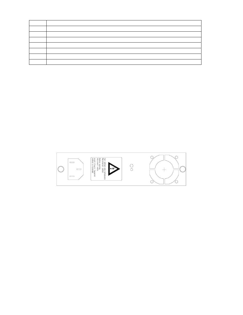
100 – 240V
AC
module
Figure 15 provides a view on the 100 – 240V
AC
power supply and fan module. The module includes an AC main input.
One LED indicates the status of the power supply module. The power unit O.K. LED lights green when the power
supply module is working properly. The power supply and fan modules can be exchanged during operation (hot
plug-in technology) without harming the equipment or having any impact on the operation of the transmitter in case of
a properly working backup power supply.
Figure 15 — 100-240 Volts AC Power Supply Drawing
±48 V
DC
module
Figure 16 shows the ±48V
DC
power supply and fan module. The module includes a ±48V
DC
cable terminal in order to
connect the supply voltage. It is important to take care of the right polarity of the DC supply voltage, either 0 or
+48V
DC
connected to the – and + terminals, respectively or 0 and –48V
DC
connected to the + and – terminals, respec-
tively.
A fuse and a spare fuse are implemented inside the power supply and fan module and can be replaced if required. One
LED gives the status of the power supply module. The power unit O.K. LED lights green indicating that the power
supply module is working properly. The power supply and fan modules can be exchanged during operation (hot
plug-in technology) without harming the equipment or having any impact on the operation of the transmitter in case of
a properly working backup power supply.