Principle of operation – Olson Technology MUSCLE-EM55X User Manual
Page 8
OTOT-EM55X/XL Optical Transmitter Rev. x1
www.olsontech.com
7
The OTOT-EM55X provides plug in power supply modules. The minimum configuration is one power supply with fan
module together with a redundant fan-only module. Optionally two power supply with fan modules can be used for
improved reliability. The power supply modules can be ordered for 100 ... 240 V
AC
and ±36 ... ±60 V
DC
. The
OTOT-EM55X accommodates one power supply and Model OTOT-EM55XL accommodates two power supplies,
which can be specified with mixed AC and DC power supplies.
Optical connectors are SC/APC standard with FC/APC optional.
For an EMS (element management system) or a NMS (network management system) an Ethernet 10/100 Mbps inter-
face is available at the rear side of the OTOT-EM55XL. This Ethernet interface supports SNMP and HTTP protocols.
The IP address for the Webserver interface can be set using the push buttons at the front panel or the RS232 local
set-up port at the rear side. An additional RS485 (master) interface has been implemented at the OTOT-EM55XL to
poll other equipment like EDFA’s or optical switches, which are connected to the local RS485 management bus. The
units may be ordered with one general purpose I/O port and four input-only ports for additional alarm or remote func-
tions. These I/O ports are accessible via the Webserver interface.
The OTOT-EM55XL offers two RS485 (slave) interfaces for EMS or NMS. An external level converter from RS485
to RS232 can be offered on request to connect the OTOT-EM55X/XL to standard PC-COM1 or -COM2 interfaces.
Furthermore, there is one alarm output, which can be used for simple alarm messaging functions.
Principle of Operation
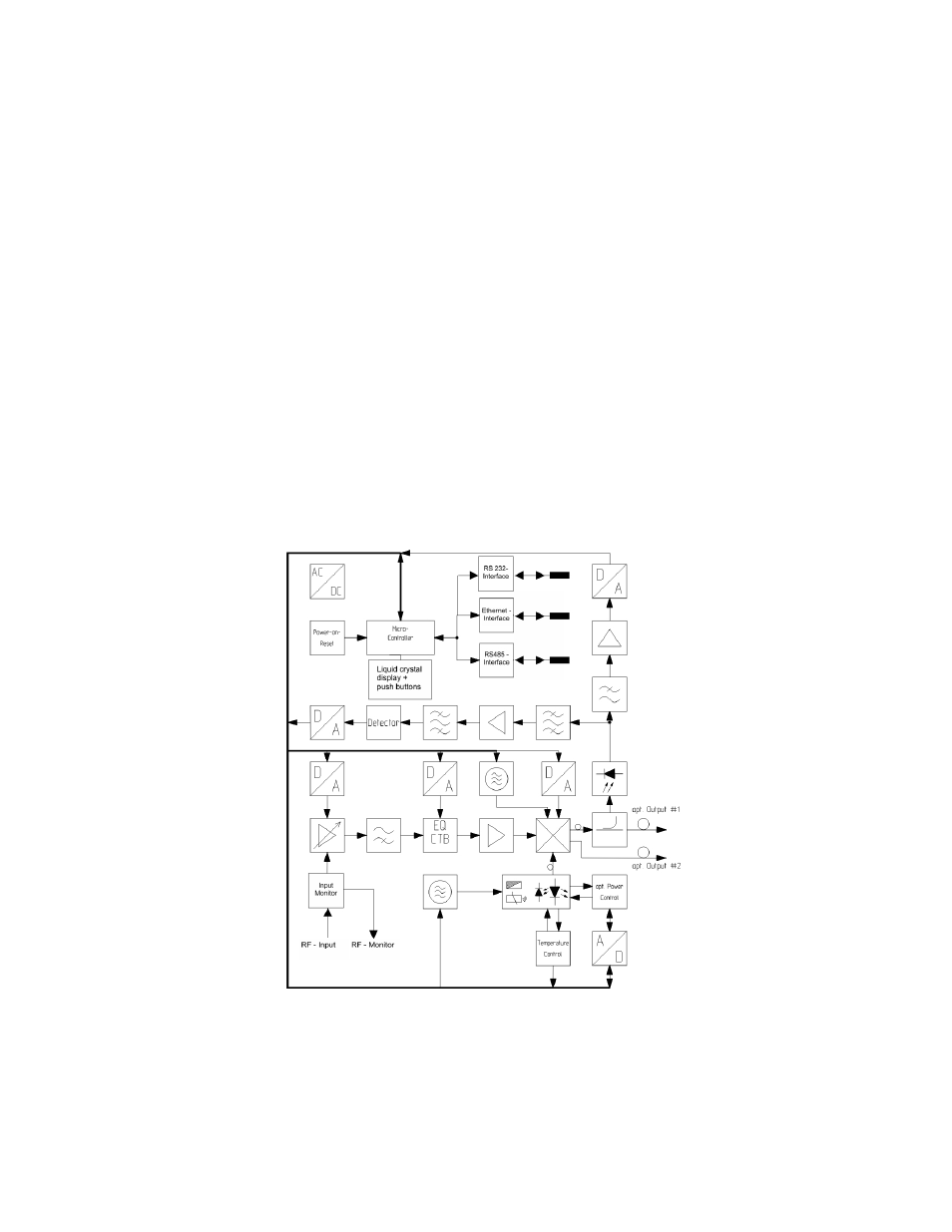
The transmitter is based on five functional blocks: RF-path, CW-DFB-laser diode, integrated optical modulator, con-
trol electronics and power supply. The functional diagram is given in Figure 2.
Figure 2 — Transmitter Functional Block Diagram
The RF input signal is fed into a preamplifier comprising an automatic gain control circuitry. The AGC stabilizes the
output signal of the preamplifier to maintain a stable RMS (root-mean-square) optical modulation index (OMI) of the
optical modulator. Input level variations are compensated as long as the AGC circuit is working in its nominal gain
range.
The AGC can be turned off for a constant gain operation via the push buttons, or the Ethernet interface in order to tai-