ONICON F-3200 Series User Manual
Page 27
11451 Belcher Road South, Largo, FL 33773 • USA • Tel +1 (727) 447-6140 • Fax (727) 442-5699 • [email protected]
F-3200 Flow Meter Manual 05/14 - 0671-12 / 18325
Page 27
3.3.3 Power and Output Signal Wiring Instructions
Factory Default Output Configurations
ONICON pre-programs the analog and pulse outputs based on application specific data
provided at the time the meter is ordered. The tables on the next page show how the pulse
outputs are configured based on whether the application has bi-directional flow and if the
meter will be connected to an ONICON peripheral device such as an ONICON BTU meter
or display module.
In all applications the analog 4-20 mA output is available at:
Analog Output #1: terminals 9 (+) and 10 (-).
Analog Output #2: terminals 28 (+) and 20(-) - Optional output available only if
the meter was ordered with the redundant output option.
Application
Pulse Output #1
Terminals: 16 (+) & 17 (-)
Pulse Output #2
Terminals: 18 (+) & 19 (-)
Standard
Frequency
Scaled Pulse
Bi-directional
*Scaled Output
Flow Direction
* This output will be configured for frequency if the flow meter is provided with a peripheral device.
Optional Auxiliary Pulse Outputs
Application
Pulse Output #3, Terminals: 22 (+) & 21(-)
Pulse Output #4, Terminals: 30(+) & 29(-)
Standard
Flow Direction
OFF
Bi-directional
Flow Direction
OFF
* This output will be configured for frequency if the flow meter is provided with a peripheral device.
Pulse Out 1
Pin 16 - Pos (+)
Pin 17 - Neg (-)
Pulse Out 2
Pin 18 - Pos (+)
Pin 19 - Neg (-)
4-20 mA Output 1
Pin 9 - Pos (+)
Pin 10 - Neg (-)
SIGNAL CONNECTIONS
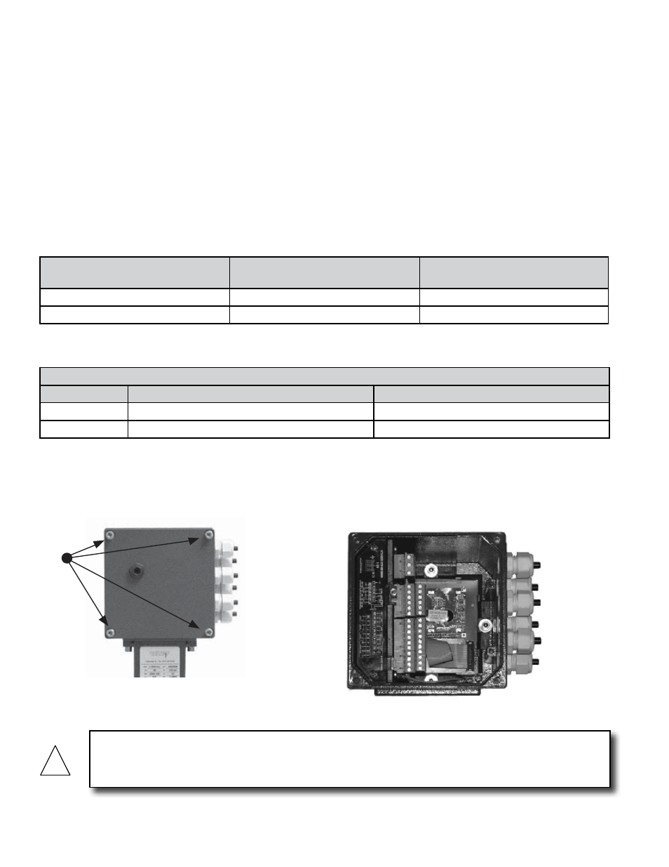
Step 1:
Remove the 4 Allen screws using a 5mm
Allen wrench.
Step 2:
Remove the cover exposing the
connection terminals.
Step 3:
Make SIGNAL connections as shown
Pull straight out on connectors to remove them.
Pulse Output 1 / 2 / 3 / 4
Opto-coupled open collector pulse outputs
Maximum voltage: 40VDC
Maximum current: 100mA
Maximum saturation voltage
collector/emitter @ 100mA: 3 VDC
Maximum Frequency: 1,250 Hz
connection terminals.
AUX SIGNAL CONNECTIONS
4 - 20 mA Output 2
Pin 28 - Pos (+)
Pin 20 - Neg (-)
Pulse Out 3
Pin 22 - Pos (+)
Pin 21 - Neg (-)
Pulse Out 4
Pin 30 - Pos (+)
Pin 29 - Neg (-)
16 (out1)
18 (out2)
22 (out3)
30 (out4)
17 (out1)
19 (out2)
21 (out3)
29 (out4)
!
CAUTION
The transmitter earth connection at the input voltage terminals and the sensor body earth terminals
must both be connected to earth to ensure proper operation.