ONICON F-3200 Series User Manual
Page 28
11451 Belcher Road South, Largo, FL 33773 • USA • Tel +1 (727) 447-6140 • Fax (727) 442-5699 • [email protected]
F-3200 Flow Meter Manual 05/14 - 0671-12 / 18325
Page 28
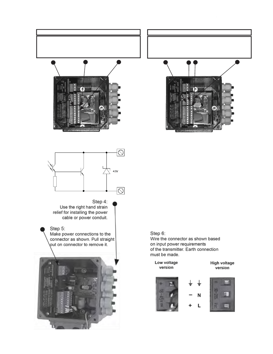
Pulse Out 1
Pin 16 - Pos (+)
Pin 17 - Neg (-)
Pulse Out 2
Pin 18 - Pos (+)
Pin 19 - Neg (-)
4-20 mA Output 1
Pin 9 - Pos (+)
Pin 10 - Neg (-)
SIGNAL CONNECTIONS
Step 1:
Remove the 4 Allen screws using a 5mm
Allen wrench.
Step 2:
Remove the cover exposing the
connection terminals.
Step 3:
Make SIGNAL connections as shown
Pull straight out on connectors to remove them.
Pulse Output 1 / 2 / 3 / 4
Opto-coupled open collector pulse outputs
Maximum voltage: 40VDC
Maximum current: 100mA
Maximum saturation voltage
collector/emitter @ 100mA: 3 VDC
Maximum Frequency: 1,250 Hz
connection terminals.
AUX SIGNAL CONNECTIONS
4 - 20 mA Output 2
Pin 28 - Pos (+)
Pin 20 - Neg (-)
Pulse Out 3
Pin 22 - Pos (+)
Pin 21 - Neg (-)
Pulse Out 4
Pin 30 - Pos (+)
Pin 29 - Neg (-)
16 (out1)
18 (out2)
22 (out3)
30 (out4)
17 (out1)
19 (out2)
21 (out3)
29 (out4)