Remko cmf / cmt, Installation instructions, System design – REMKO CMF-80 v.2 User Manual
Page 10
REMKO CMF / CMT
Installation instructions
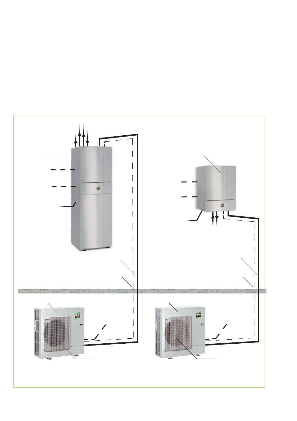
The indoor and outdoor modules
have to be connected with refrigerant
lines of dimensions
3
/
8
" and
5
/
8
".
System design
Outdoor unit
Indoor
module CMT
Series
fan
Outdoor area
Refrigerant lines
3
/
8
" and
5
/
8
"
Mains cable
Interior 3x
Draining pan
Indoor area
Condensate drain
(must be designed to be frost proof!)
* Mains supply
3x230V/1~/50Hz 25A
electrical connection
4x
Domestic water 1"
Hot water 1"
Outdoor unit
fan
Condensate drain
(must be designed to be frost proof!)
electrical connection
4x
Indoor module
CMF Series
Mains cable
Interior 3x
Condensation line
Hot water 1"
A four-wire control cable has to be
laid between the two modules.
Both the indoor and outdoor
modules require a separate power
supply.
* Mains supply
3x230V/1~/50Hz 25A
Refrigerant lines
3
/
8
" and
5
/
8
"
* Mains power supply 5x for outdoor modules CMF 140, CMF 150 and CMT 150: 400V/3~N/50Hz 16A
optional mains
power line
Electric heating
230V or 400V
Mains cable
Electric heating
230V or 400V
Domestic water 1"
10