RLE FMS User Manual
Fms sensor wiring guide, 50 – 95 degree f range, Sheet: 1 of 16
SHEET:
1 OF 16
104 Racquette Drive
Fort Collins, CO 80524
(970) 484-6510 Phone
(970) 484-6650 Fax
www.rletech.com
FMS Sensor Wiring Guide
10061_FMS Rev 2.0 (8/13)
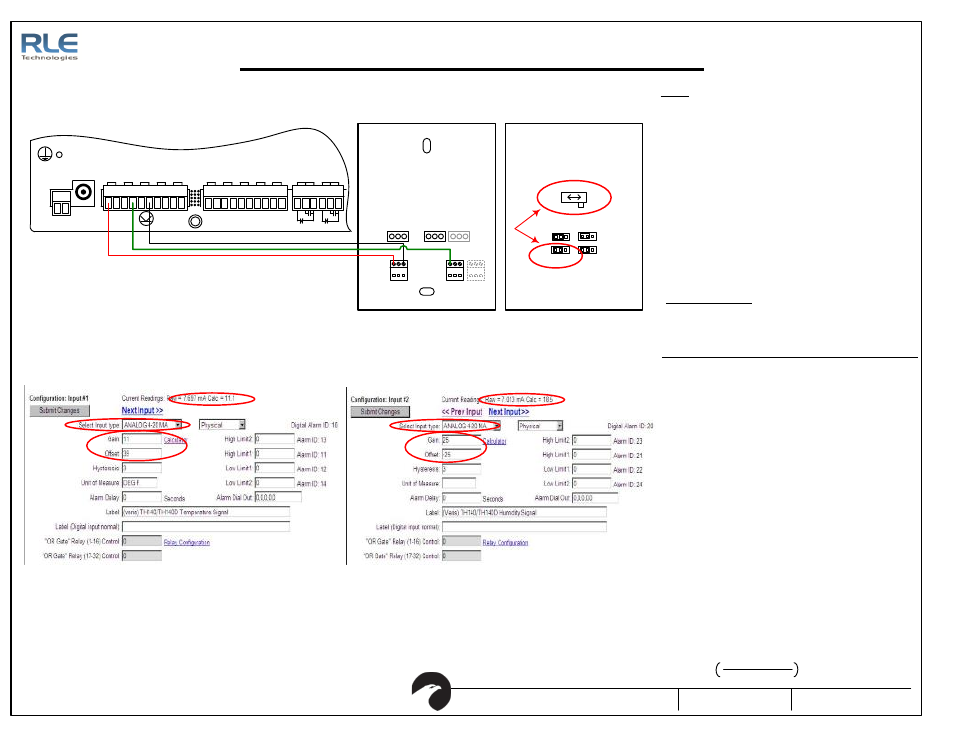
FMS to TH140/TH140D Integration
Figure 1.2: Temperature Setup
Figure 1.3: Humidity Setup
1. Set the switch positio n to mA. Set the temperature ran ge to
50-95 or 32-122. The Sensor is shippe d from th e facto ry with
the switch in the volts po sition and the te mp erature range is
set for 50-95F. The switch po sition must be se t to the mA
position.
2. Wire th e sensor as shown.
5. Ver ify the "Calc" Valu e d isp lays th e corre ct r oom tempera ture .
The tempe rature can also be viewed on the Falcon ma in page.
SETUP
1. Calculate the TH140 Output cur rent for te mpe rature.
TRO UBLESHOO TING
2. Measure th e curr ent flowing into the Falcon Ch- terminal with a
current me ter. Ver ify that it is close to the calcula ted curren t
(+/-1%)
Example if Room Te mp is 70F an d you r sensor has a ra nge of 50-95
3. If measured current curr ent do es not ma tch calcula ted curren t
then ch eck wi ring and check TH140/TH140D ju mp er a nd switch
settings.
4. Compare the me asu red cur rent matches the cu rrent re ading in
the Fal con.
5. Check the wir ing if th e Falcon current readin g d oes no t match
the me asu red cu rrent re ading.
6. If th e Falcon current readin g matches the measured current
and the Fa lco n calculated value does not match the room
temperature then the offset and gain values are wr ong.
Double check the Gain and Offset va lues.
7. If th e tempera ture di spla ye d in the Fa lco n is 1 or 2 deg rees
abo ve or belo w th e r oom tempera ture then adju st the offset b y
1 or 2. Do not adj ust the ga in. Onl y tweak th e o ffse t once the
previou s tr oubleshoo tin g steps ha ve bee n p erfo rmed.
8. If th e Falcon still doe s not d isp lay the cor rect te mp erature
contact RL E Techno logies technical suppor t at 970.484.651 0.
9. Use similar tro ubleshoo ting pro ce dure excep t use the
following formula to calculate the humidity mA output.
mA =
Room Humidi ty
100
x 16 + 4
P1
VDC
TB 1
VDC
+ -
EXT ERNAL
24VDC
+ +
Ch1
+ -
Ch2
+ -
Ch3
+ -
Ch4
+ -
TB 2 Inp ut 1-4
Ch5
+ -
Ch6
+ -
Ch7
+ -
TB 3 Inp ut 5-8
Ch8
+ -
EXT ERNAL
GND
- -
TB 4
NC NO C
RELAY 1
NC NO C
RELAY 2
P
W
R
(4
-20
S
E
N
D
)
C
O
M
M
O
N
R
H
O
U
T
(
4
-20
R
T
N
)
T
O
U
T
(
4
-20
R
T
N
)
R
T
D
/O
V
E
R
R
ID
E
R
T
D
/O
V
E
R
R
ID
E
S
L
ID
E
R
R
IG
H
T
S
L
ID
E
R
W
IP
E
R
S
L
ID
E
R
L
E
F
T
B ACK P IE CE
CENT ER P IE CE (WI TH CIRCUIT B OARD )
S W1
mA
V olts
TE MP 10/5V
TE MP RA NGE
50-95/32-122
TE MP F /C
Out put S elec t
RH 10/5V
Figure 1.1: FMS Wiring with the TH140/TH140D
1
3. Configure the Fa lcon Input cha nnel (temperature) for "Ana log
4-20mA" and en ter the Gain and Offset valu es. For the 50-95F
rang e u se Ga in 11.25, Offset 38.75. For 32-122F ra nge use
Gai n 22, Offset 10.
4. Configure the Fa lcon Input Ch annel (humidity) for "Ana log 4-
20mA" and en ter the Gain of 25 and Offset of -25.
3
4
5
5
2
( (
Act ual t emp - Sensor Low
) / (
Sensor High - Sensor Low
)) x 16 + 4
( (70 - 50) / (95 - 50)) x 16 + 4 = 11.11
Formula for calculating the correct RAW value
50
– 95 Degree F Range