Fms_teams, Fms to teams integration, Fms sensor wiring guide – RLE FMS User Manual
Page 4: Figure 4.2: temperature setup, Figure 4.1: fms wiring with the teams, 50 – 95 degree f range
SHEET:
4 OF 16
104 Racquette Drive
Fort Collins, CO 80524
(970) 484-6510 Phone
(970) 484-6650 Fax
www.rletech.com
FMS Sensor Wiring Guide
10061_FMS Rev 2.0 (8/13)
FMS to TEAMS Integration
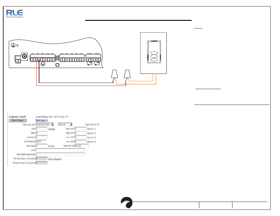
Figure 4.2: Temperature Setup
1. The tempe rature range is 50-95 deg F
2. Wire th e sensor as shown.
Ora nge wi res are po larity inde penden t
4. Ver ify the "Calc" Valu e d isp lays th e corre ct r oom tempera ture .
The tempe rature can also be viewed on the Falcon ma in page.
SETUP
1. Calculate the output cur rent for te mpe rature.
TRO UBLESHOO TING
2. Measure th e curr ent flowing into the Falcon Ch- terminal with a
current me ter. Ver ify that it is close to the calcula ted curren t
(+/-1%)
Example if Room Te mp is 70F an d you r sensor has a ra nge of 50-95
3. If measured current curr ent do es not ma tch calcula ted curren t
then ch eck wi ring.
4. Compare the me asu red cur rent matches the cu rrent re ading in
the Fal con.
5. Check the wir ing if th e Falcon current readin g d oes no t match
the me asu red cu rrent re ading.
6. If th e Falcon current readin g matches the measured current
and the Fa lco n calculated value does not match the room
temperature then the offset and gain values are wr ong.
Double check the Gain and Offset va lues.
7. If th e tempera ture di spla ye d in the Fa lco n is 1 or 2 deg rees
abo ve or belo w th e r oom tempera ture then adju st the offset b y
1 or 2. Do not adj ust the ga in. Onl y tweak th e o ffse t once the
previou s tr oubleshoo tin g steps ha ve bee n p erfo rmed.
8. If th e Falcon still doe s not d isp lay the cor rect te mp erature
contact RL E Techno logies technical suppor t at 970.484.651 0.
P1
VDC
TB 1
VDC
+ -
EXT ERNAL
24VDC
+ +
Ch1
+ -
Ch2
+ -
Ch3
+ -
Ch4
+ -
TB 2 Inp ut 1-4
Ch5
+ -
Ch6
+ -
Ch7
+ -
TB 3 Inp ut 5-8
Ch8
+ -
EXT ERNAL
GND
- -
TB 4
NC NO C
RELAY 1
NC NO C
RELAY 2
Figure 4.1: FMS Wiring with the TEAMS
3. Configure the Fa lcon Input cha nnel (temperature) for "Ana log
4-20mA" and en ter the Gain and Offset valu es. For the 50-95F
rang e u se Ga in 11.25, Offset 38.75.
3
5
( (
Act ual t emp - Sensor Low
) / (
Sensor High - Sensor Low
)) x 16 + 4
( (70 - 50) / (95 - 50)) x 16 + 4 = 11.11
Formula for calculating the correct RAW value
50
– 95 Degree F Range
Tem perat ure Si gnal .