Afs-d, Afs-d fms integration, Fms sensor wiring guide – RLE FMS User Manual
Page 9: Figure 9.1: fms wiring
Advertising
SHEET:
9 OF 16
104 Racquette Drive
Fort Collins, CO 80524
(970) 484-6510 Phone
(970) 484-6650 Fax
www.rletech.com
FMS Sensor Wiring Guide
10061_FMS Rev 2.0 (8/13)
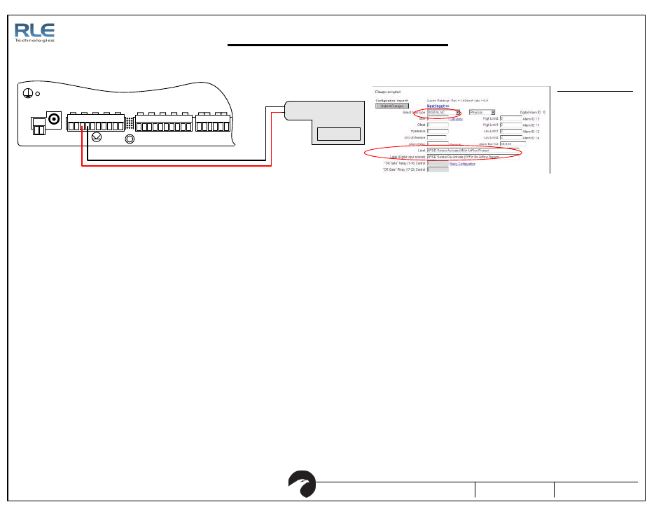
AFS-D FMS Integration
Set Input Type to a NC
Digital Contact for each
AFS-D wired into the
Falcon. Assign an on/
off label for each sensor
connected.
FMS Configuration
Figure 9.1: FMS Wiring
P1
V DC
TB 1
V DC
+ -
EXT ERNAL
24VDC
+ +
Ch1
+ -
Ch2
+ -
Ch3
+ -
Ch4
+ -
TB 2 Input 1-4
Ch5
+ -
Ch6
+ -
Ch7
+ -
TB 3 Input 5-8
Ch8
+ -
EXT ERNAL
GND
- -
TB4
NC NO C
RELAY 1
NC NO C
RELAY 2
FMS Input Configuration Interface
Advertising