Sensoray 526 User Manual
Page 12
12
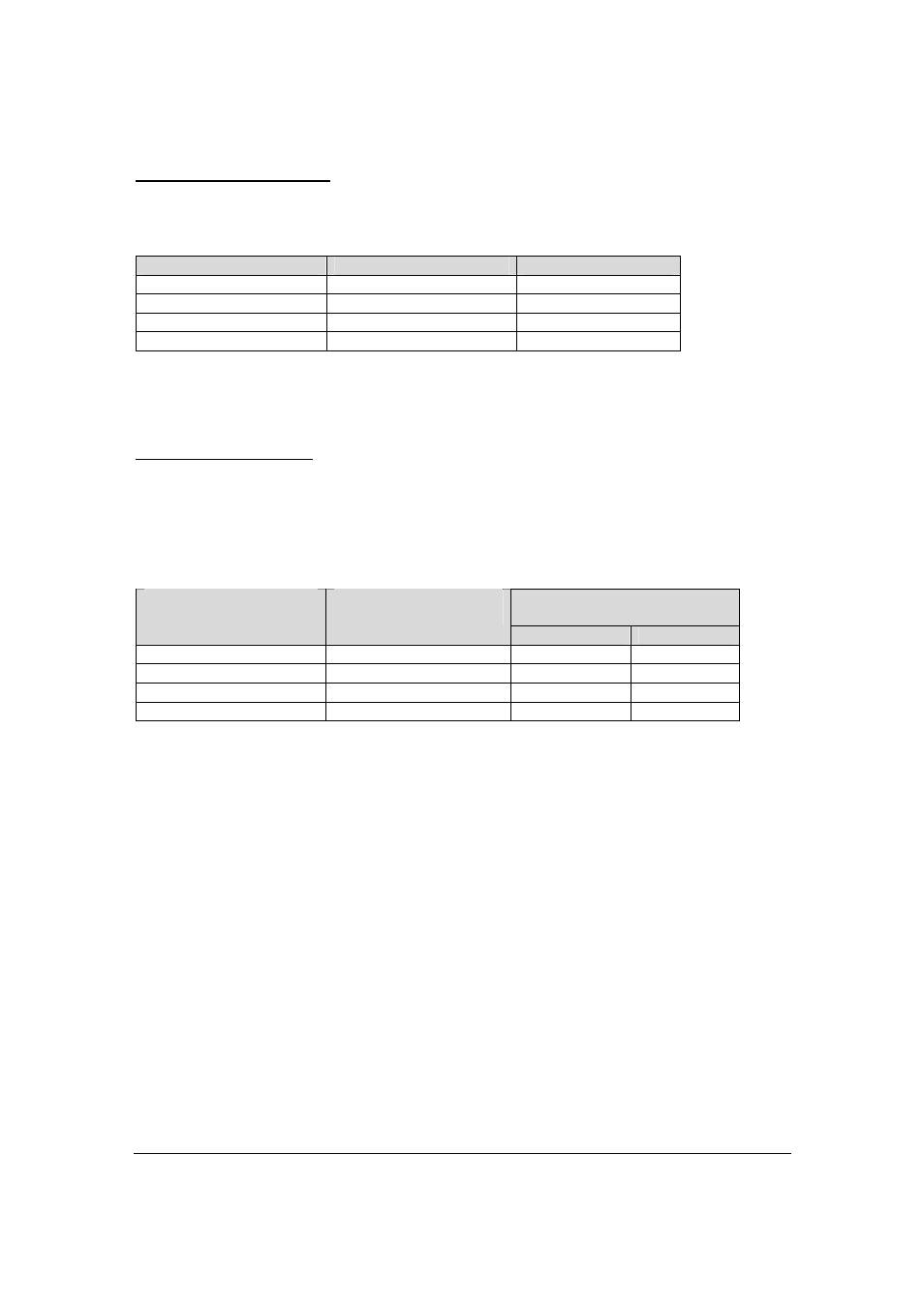
Watchdog enable/disable
Watchdog enable/disable is controlled by bit [3] of the Watchdog Timer Control register and
jumper 1 of J4.
Shunt in position 1 of J4
Bit [3] of Control Register
Watchdog timer
Not installed
0
Disabled
Not installed
1
Enabled
Installed
0
Enabled
Installed
1
Disabled
Bit [3] is always 0 after power up, so if the watchdog timer has to be enabled by default, the
shunt has to be installed.
Solid-sate relay control
The polarity of the watchdog timer output signal (CONTROL on Fig.3) is controlled by bit [4] of
the Watchdog Timer Control register and jumper 2 of J4. When CONTROL is not active, each
solid-state relay is in its default (normal) state. When CONTROL becomes active, the solid-state
relays change their states.
Solid-state relay control
Shunt in position 2 of J4
Bit [4] of Control
Register
Timed out
Not timed out
Not installed
0
Active
Not active
Not installed
1
Not active
Active
Installed
0
Not active
Active
Installed
1
Active
Not active