Sensoray 526 User Manual
Page 26
26
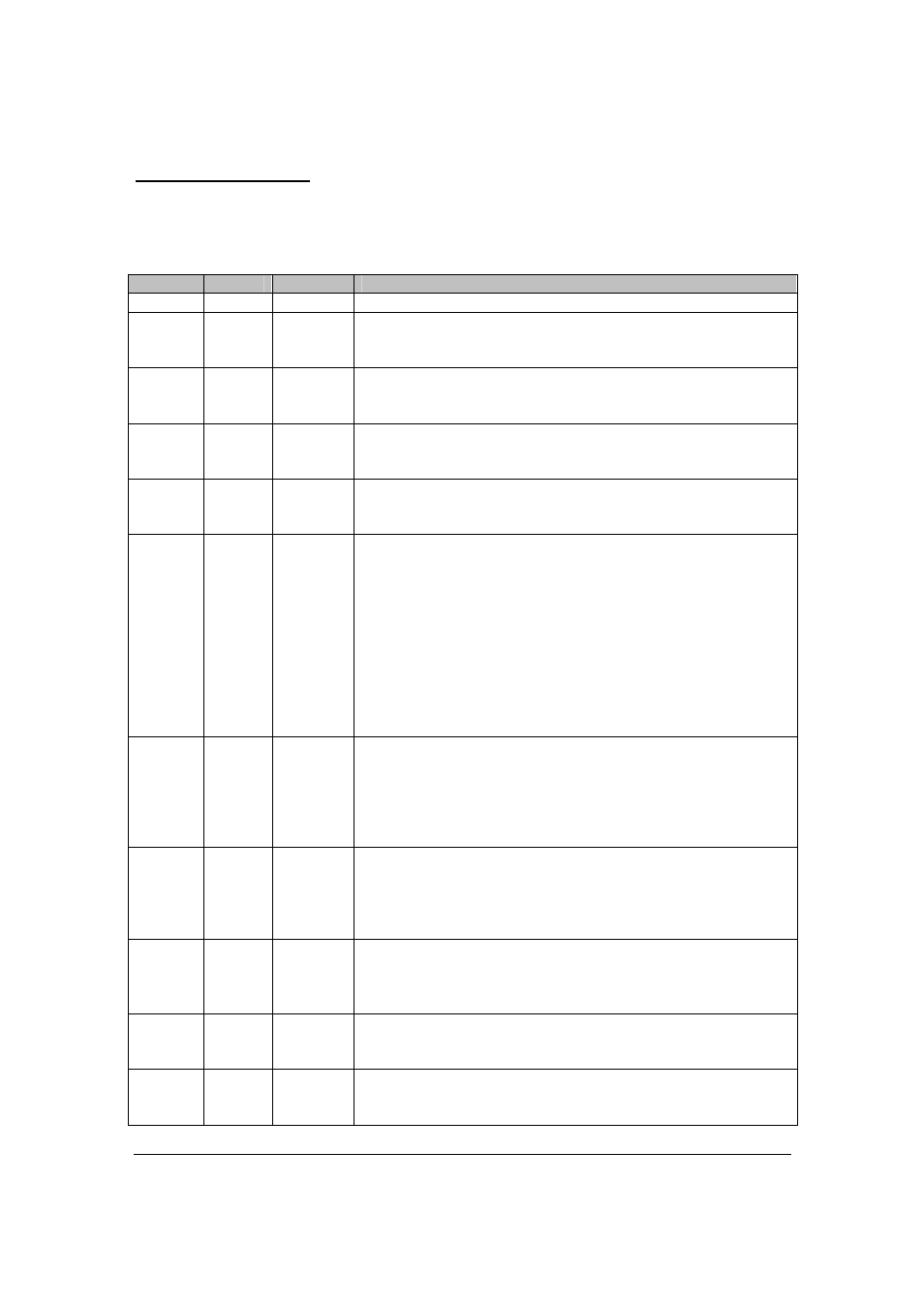
Counter Mode Register
0x16 – counter 0,
0x1E – counter 1,
0x26 – counter 2,
0x2E – counter 3.
Bits
Type
Default
Description
[15]
UU
X
Reserved.
[14]
WO
0
Preload register select:
0 – writes to Preload Register directed to PR0;
1 – writes to Preload Register directed to PR1.
[13]
WO
0
Output register latch control:
0 – latch on read (Note 1);
1 – latch on event (Note 2).
[12]
WO
0
Count direction control:
0 – quadrature (dependent on CLKA-CLKB relative phase);
1 – software control.
[11]
WO
0
Count direction if [12]=1, no effect if [12]=0:
0 – up;
1 – down.
[10:9]
WO
00
Clock source:
If [12]=0:
00 – quadrature x1 (CLKA
↑
counting up, CLKA
↓
counting
down);
01 – quadrature x2 (both edges of CLKA);
1X – quadrature x4 (both edges of both CLKA and CLKB).
If [12]=1:
00 – CLKA
↑
;
01 – CLKA
↓
;
10 – internal clock;
11 – internal clock
÷
2.
[8:7]
WO
00
Count Enable control:
00 – count disabled;
01 – count enabled;
10 – hardware Count Enable (configured with [6:5]);
11 – hardware Count Enable (configured with [6:5]), inverted
polarity.
[6:5]
WO
00
Hardware Count Enable source:
00 – CEN;
01 – INDEX;
10 – INDEX
↑
to
↓
;
11 – NOT RCAP.
[4:2]
WO
000
Auto load and reset RCAP (can be OR’ed):
[4] – INDEX
↑
;
[3] – INDEX
↓
;
[2] – RO.
[1]
WO
0
COUT polarity:
0 – normal;
1 – inverted.
[0]
WO
0
COUT source select:
0 – RCAP;
1 – RTGL.