Console calibration, Operation – Smithco Spray Star 1100e Operator Manual User Manual
Page 19
17
Operation
CONSOLE CALIBRATION
CALCULATING “BOOM CAL” (BOOM 1, BOOM 2, BOOM 3)
Calculate the width of each boom in inches (centimeters) by multiplying the number of tips times the spacing. Write
these boom widths down for future reference when programming the Console computer. The Console is capable of
controlling up to three (3) booms.
CALCULATING “SPEED CAL"
1.
Enter Speed Cal in key
of 785 in (205 dm).
2.
Place Master and Boom 1 switches to on.
3.
Enter “0” in key
.
4.
Drive 1 mile. Do not use vehicle odometer to determine distance, use section lines or highway markers.
5.
It should read a value of approximately 5280. If it reads between 5200-5350, the Speed Cal for this vehicle is
785.
If the Distance display reads any other value, divide Speed Cal by the value observed in Distance, then multiply
by 5280. This will give you the correct value to enter for Speed Cal. You must round off to the nearest 3 digit
number (use 120 not 120.3).
6.
Recheck the new Speed Cal numbers derived in Step 5 by repeating steps 2 thru 4.
MEASURE CAREFULLY. Be sure tire is properly inflated before measuring. Measure tire in type of soil in
which you will be spraying. Circumference of tire will vary when measured in soft soil versus hard
packed soil. For best results, measure several times and average the results. Re-measure periodically.
CALCULATING “METER CAL”
The Flow Meter calibration number is stamped on the label attached to each Flow Meter; this number is to be used for
gallon per area applications. To convert original METER CAL from gallons to desired units of measure (oz, lbs or liters
per area) see Abbreviations and Conversions section of this manual. Write down this calibration number for future
reference when programming the console.
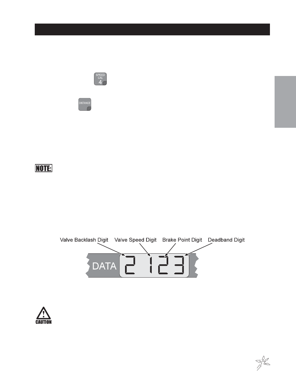
CALCULATING "VALVE CAL”
The initial Control Valve calibration number is 2123. After operating the system, you may desire to refine this number.
See definitions below.
A.
Valve Backlash Digit - Controls the time of the first correction pulse after a change in correction direction is
detected. Incr to Decr or Decr to Incr Range: 1 to 9, 1-Short Pulse, 9-Long Pulse
B.
Valve Speed Digit - Controls the Speed of the Control Valve motor.
Running the Control Valve too fast will cause the system to oscillate.
Range: 1 to 9, 1-slow, 9-Fast
C.
Brake Point Digit - Percent Sets the point at which the Control Valve motor begins braking, so as not to over
shoot the desired rate. Digit is percent away from target rate. Range: 0 to 9, 0=5%, 1=10%, 9=90%,
D.
Deadband Digit - Allowable difference between target and actual application rate, where rate correction is
not performed. Range: 1 to 9, 1 = 1%, 9 = 9%