Model 740, Master output – Studio Technologies 740 User Manual
Page 16
Issue 3, May 2004
Model 740 User Guide
Page 16
Studio Technologies, Inc.
Model 740
In the mic (out) position, the expected
nominal input level range is –55 to –35
dBu. In the line (in) position, a 43 dB pad
is inserted into the circuit, making the
expected nominal input level range –12 to
+8 dBu.
Status LED
A bicolor LED acts as a user-confidence
indication of the overall signal level in the
mic/line input channel’s circuitry. The LED
will light green as a signal present indica-
tor, showing that the input signal, along
with the gain of the input preamplifier, is
at least 18 dB below the nominal internal
operating level. The LED will light red as
a peak signal indicator, showing that the
input signal, along with the gain of the
preamplifier, is within 6 dB of the circuitry’s
maximum level.
Level Control
The rotary control is used to adjust the
gain of the input section’s preamplifier
circuitry. In the fully counterclockwise
position the preamplifier gain is set to its
minimum, and full attenuation is achieved.
This means that no signal continues on to
the mixing circuitry that creates the main
audio bus. As the level control is rotated
in the clockwise direction the gain of the
preamplifier increases.
Master Output
The Model 740’s master output section
has one LED indicator and one rotary
control associated with it.
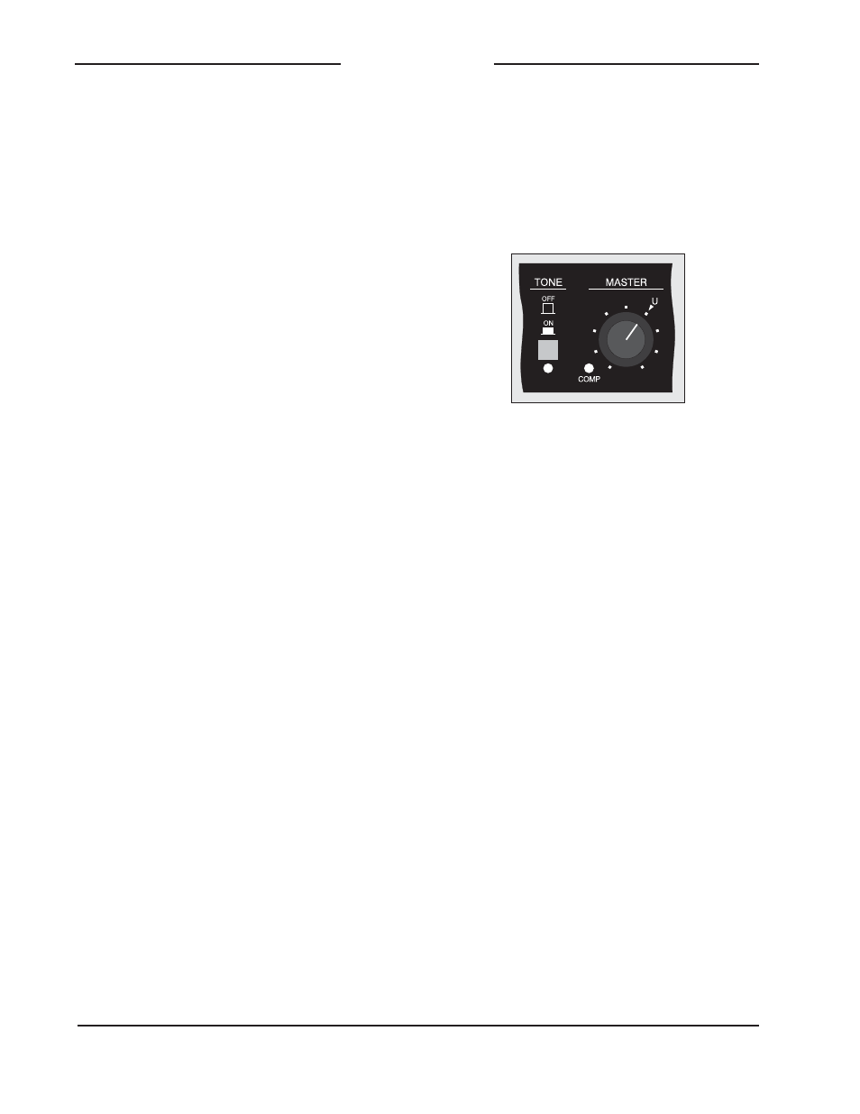
Master Level Control
One rotary control is used to set the over-
all level of the main audio bus. On the
front panel, note the graphic symbol and
the letter “U,” located at the approximately
“1-o’clock” rotational position. This indi-
cates the correct setting for the master
output section to give unity gain, and
is the position where the control should
normally be set.
Detail of front panel showing master level
control, compressor active LED, and reference
tone on/off button
Reference Tone
A sine-wave tone can be connected to
the main audio bus, serving as a reference
signal for local and remote use. A push-
button switch selects its status; when the
switch is in the on (in) position tone is con-
nected. An LED indicator, which is located
directly below the switch, lights whenever
tone is being sent to the main bus. The
distinctive blue color of the LED is in-
tended to clearly alert the user that tone
is active. The level of the tone generation
circuitry is adjusted at the factory to match
the Model 740’s internal operating level.
When the tone is connected to the main
audio bus, the master level control can be
adjusted to give a +4 dBu indication on
the level meter.
Compressor
A studio-quality compressor circuit is
associated with the main audio bus.
A yellow LED, located to the left of the
master level rotary control, lights when-
ever the compressor is controlling the