Model 740 – Studio Technologies 740 User Manual
Page 18
Issue 3, May 2004
Model 740 User Guide
Page 18
Studio Technologies, Inc.
Model 740
(Remember that 0 VU typically indicates
a device’s reference operating level—
frequently +4 dBm.) The seven green
LEDs display a dynamic range of 28 dB,
with thresholds of –24 dBu, –18 dBu,
–12 dBu, –8 dBu, –4 dBu, 0 dBu, and
+4 dBu. This is the range that typical sig-
nals should display if correct settings have
been made to the input sensitivity switch-
es, input level controls, and master level
control. The two yellow LEDs light when
the signal level has exceeded the Model
740’s nominal +4 dBu output level. Their
thresholds are +8 dBu and +12 dBu, well
within the capabilities of the unit’s circuitry.
The red LED lights when the main output
meets or exceeds +18 dBu. This is dan-
gerously close to the Model 740’s maxi-
mum output level and should be avoided.
But now back to reality when it comes to
how the meter will function during actual
Model 740 use. To a great degree meter
activity will depend on how the compres-
sor has been configured to operate. As
discussed in previous sections of this user
guide, a technician can set the Model
740’s compressor from one of the three
operating modes:
• If the factory-default compressor thresh-
old of +10 dBu is in effect with normal
audio content the meter will probably
show a moderate amount of impact
caused by the dynamic range control.
The two yellow LEDs may light on peak
signal levels, along with the compressor
active LED. The red LED will essentially
never light.
• If the threshold is set for +6 dBu, typi-
cally only the first yellow LED will light.
The second yellow LED will rarely light.
And the red LED will probably never
light. With this configuration there often
may be a lot of dynamic range control
being performed by the compressor.
Obviously the goal is for the operator to
carefully set the Model 740’s controls
so that the signal level generally stays
below the compressor’s threshold. But
with the fairly low threshold of +6 dBu,
it may be difficult to not have the com-
pressor active almost all the time.
• If the compressor has been configured
not to function (disabled), the meter
will get its biggest workout. Depending
on the setting of the input and master
output controls, all ten segments of the
meter will come into play.
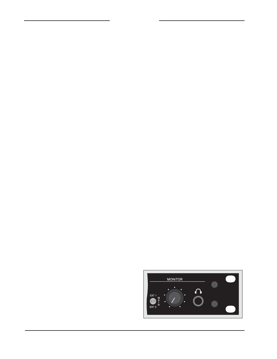
Monitor Section
The monitor section can assist an operator
in obtaining the best performance from
the Model 740 and its associated equip-
ment. The monitor section supports both
loudspeaker and headphone devices.
The monitor output is line level and is
designed to be connected to an audio
power amplifier and associated loud-
speaker. Alternatively, it can be connected
to an “amplified” loudspeaker that con-
tains an internal power amplifier. Separate
headphone outputs are provided, one on
the front panel and one on the back panel.
A 3-position toggle switch selects which
signal is presented to the monitor output,
the headphone outputs, and, if configured,
the 10-segment LED level meter.
Detail of front panel showing monitor section