Model 740, Level meter – Studio Technologies 740 User Manual
Page 17
Model 740 User Guide
Issue 3, May 2004
Studio Technologies, Inc.
Page 17
Model 740
dynamic range of the main bus. The oper-
ating threshold of the compressor and
associated LED depends on how the
Model 740 has been configured:
• From the factory the compressor
threshold is set to be 6 dB over the
Model 740’s nominal operating level.
This correlates to a level on the main
output connector of +10 dBu.
• The compressor’s configuration can
also be revised so that the threshold
is 2 dB over nominal. This correlates
to a nominal level on the main output
connector of +6 dBu. With this configu-
ration the compressor may be active
quite frequently during typical Model
740 operation.
• A third configuration is also available
which serves to disable the compressor.
In this case dynamic range control will
never take place and the LED will never
light.
If the configuration is set to use one of
the two thresholds, i.e., the compressor
is not disabled, the compressor active
LED should prove useful. With the input
and master output level controls set cor-
rectly, the compressor active LED should
light only when peak signals are present.
For maximum audio fidelity during typical
Model 740 use, the LED should not light
or should light infrequently.
Level Meter
A 10-segment LED level meter displays
the level of the main output. And, depend-
ing on the Model 740’s internal configu-
ration, it may also be able to display the
level of the two external monitor inputs.
The seven green LEDs will light in the
presence of signals in the normal operat-
ing range. The two yellow LEDs will light
with signals slightly higher than normal.
The red LED will light whenever the signal
level is in the “headroom” area. The ballis-
tics of the meter is a cross between that
of a VU and a peak (PPM) meter. (We af-
fectionately refer to it as a “PU” meter!)
The way the LEDs “move” in response to
signals should be comfortable for most
users to observe.
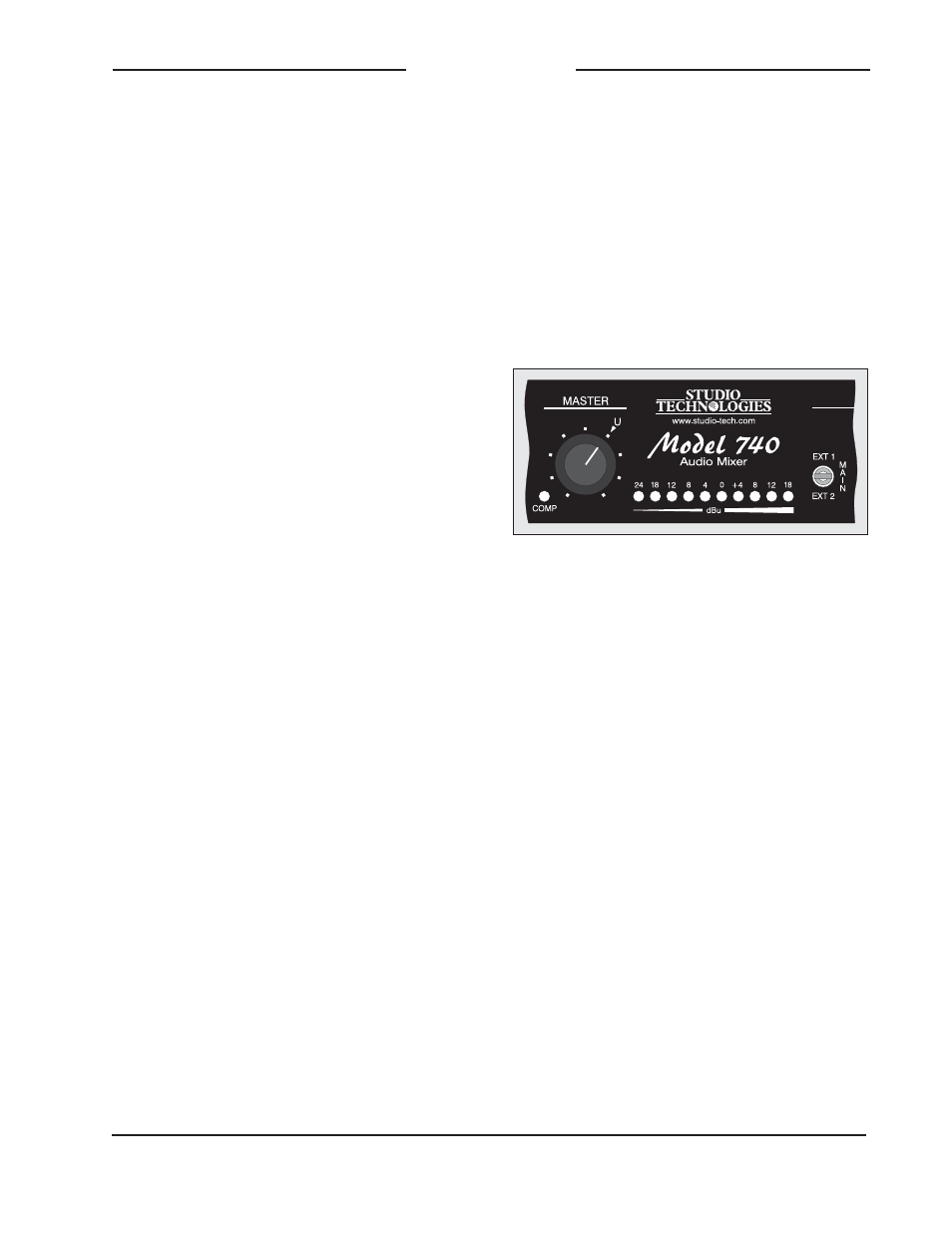
Detail of front panel highlighting 10-segment
LED level meter
Meter operation depends on the internal
configuration of the meter source mode.
A technician can select from one of two
choices: main output only or monitor
source select switch. From the factory
the meter is set to always display the level
of the main output. Alternately, the meter
can be configured to “follow” the source
selected for the monitor output. In this
way the level of either the main output,
or either of the external monitor inputs,
can be displayed.
While the meter is easy to interpret,
it’s somewhat different from one that
is marked with “VU” nomenclature. The
important thing to remember is that the
steps show level in dBu, rather than VU
units. So, for example, when the meter
step that is labeled “0” lights, it indicates
that 0 dBu is present on the main output
connector. It doesn’t indicate 0 VU!