Model 770 – Studio Technologies 770 User Manual
Page 34
Issue 1, October 1997
Model 770 User Guide
Page 34
Studio Technologies, Inc.
Model 770
LED meter. This is because the mechani-
cal meter is slower in responding to
signal peaks. With a more constant signal,
such as a tone, the meters will display
essentially identical levels.
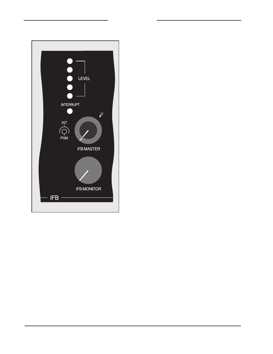
IFB Master Level Controls
Two controls are used to set the master
levels of the IFB audio buses. The inner
knob controls the level of the program
audio bus; the outer controls the interrupt
audio bus. In most cases simply setting
the controls to the unity gain position, as
marked on the front panel, will provide the
best performance. During actual operation
there is absolutely no problem adjusting
the controls to give the desired program-
to-interrupt level balance, along with
keeping the LED meter lighting in the
normal range; the green LEDs lighting
regularly, with an occasional lighting of
the yellow LED.
Telephone Interface
Three status LEDs, three switches, and
one trim potentiometer are associated with
the telephone interface. The yellow LED,
labeled STANDARD AUDIO, is lit whenever
the interface is set for the standard audio
mode. This occurs when the second pair
(pins 2 and 5) of the telco interfaces
modular jack are shorted (connected
together). The red LED, labeled RING,
lights whenever a high-voltage ringing
signal is detected on the input to the telco
interface. The green LED, labeled OFF-
HOOK, lights whenever DC loop current
is flowing through the interface. If the
interface is set for the standard audio
mode and DC current is detected, the off-
hook LED will light in a flashing on-and-off
cadence. This is to indicate an abnormal
condition, one that requires the mode of
the interface to be changed to the tele-
phone line mode.
The interface control switch, active in the
telephone line mode, allows the interface
to be manually answered or hung up.
Momentarily pressing the switch to the
position labeled ANSWER places the
interface in the off-hook state, and causes
a one-second acknowledgment tone to
be sent out the interface. If DC current
is detected, the interface will stay in the
off-hook state and the off-hook LED will
light. If loop current is not detected, the
Figure 14. Detail of front panel showing IFB
master section