Jumper positions – modbus rtu/ascii – Super Systems H2 Sensor User Manual
Page 6
Hydrogen (H
2
) Sensor Operations Manual
Super Systems Inc.
Page 6 of 17
ADDRESS 1
ADDRESS 2
ADDRESS 3
ADDRESS 4
1
O
1
O
1
O
1
O
2
N
2
N
2
N
2
N
3
3
3
3
4
4
4
4
ADDRESS 5
ADDRESS 6
ADDRESS 7
ADDRESS 8
1
O
1
O
1
O
1
O
2
N
2
N
2
N
2
N
3
3
3
3
4
4
4
4
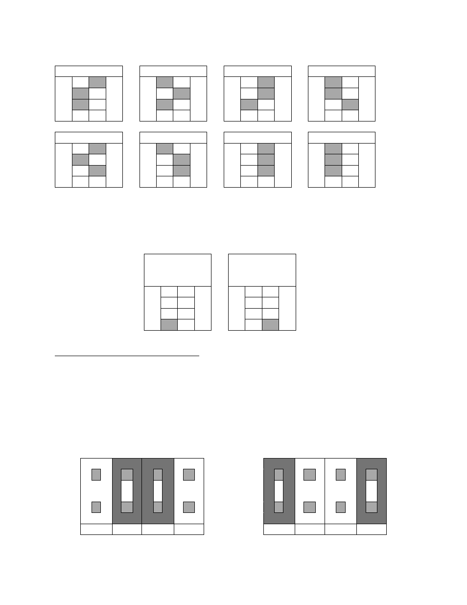
Figure 3 - Dip Switch Settings (#1, #2, #3)
The last dip switch (#4) indicates the communication protocol. The ‘Off’ position is Modbus RTU
mode, and the ‘On’ position emulates the simple ASCII protocol of the previous version of the
SSI Hydrogen Sensor. The diagram below describes the switch position for each protocol. The
shaded area indicates the location of the switch.
Modbus RTU
Protocol
Previous SSI
Sensor
Protocol
1
O
1
O
2
N
2
N
3
3
4
4
Figure 4 - Dip Switch Positions (#4)
Jumper Positions – Modbus RTU/ASCII
(Item “D” in Figure 2)
Four jumper terminals can be found on the board approximately 1.5” (3.81cm) to the left of the
RS-485 connections (specifically, when looking at the board in the orientation shown in Figure
2). These jumpers determine the pins that transmit and receive data via RS-232 communication.
The jumpers should be on Pins 2 and 3 for normal Modbus RTU operation (pin 2 is receiving and
pin 3 is transmitting). The jumpers should be on Pins 1 and 4 if the sensor is being used to
communicate via the simple ASCII protocol used on the previous version of the SSI Hydrogen
Sensor (pin 2 is transmitting and pin 3 is receiving).
Modbus RTU Protocol
1
2
3
4
Simple ASCII Protocol
1
2
3
4
Figure 5 - Jumper Positions (Modbus RTU/ASCII)