Pin connector, Analog output jumpers, Pin connector analog output jumpers – Super Systems H2 Sensor User Manual
Page 7: Analog output jumpers” below
Hydrogen (H
2
) Sensor Operations Manual
Super Systems Inc.
Page 7 of 17
9-Pin Connector
(Item “E” in Figure 2)
The sensor has a female 9-pin connector used for RS-232 communication. Only three of the
nine pins are used, and their assignments are:
Pin #2: Transmit or Receive (Depends on jumper positioning)
Pin #3: Transmit or Receive (Depends on jumper positioning)
Pin #5: Ground
Analog Output Jumpers
(Item “F” in Figure 2)
Jumpers near the analog output terminal block are used to determine whether a current or a
voltage is produced. Figure 6 shows the locations of the four jumpers: JP2, JP3, JP4, and JP5.
JP2
V1
JP4
V2
JP3
0-5V
JP5
0-5V
Figure 6 - Layout of Analog Output Jumpers
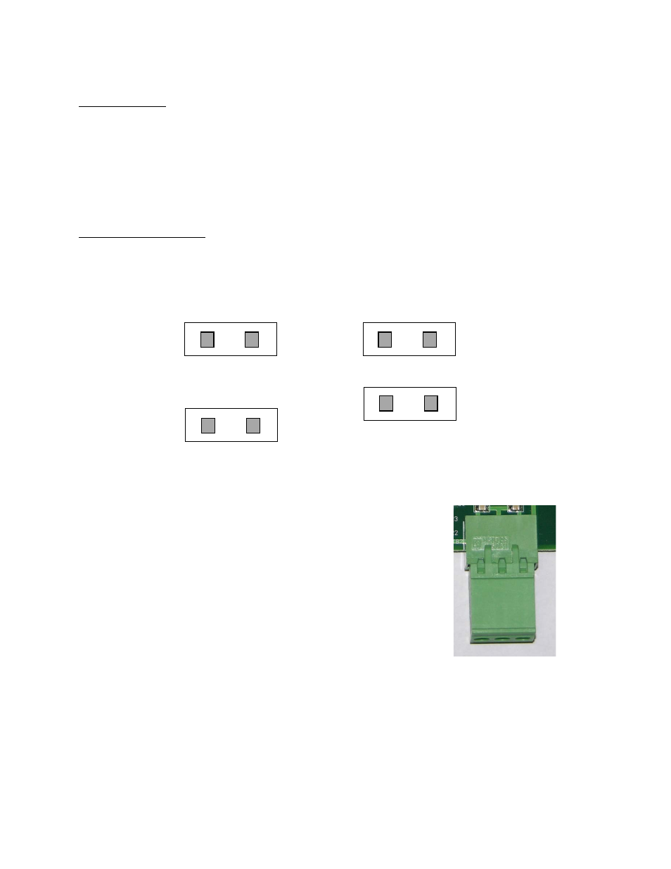
If all jumpers are OPEN, a 4-20mA signal is produced.
Note the location of terminals #1 and #2, as well as the
COMMON terminal, in Figure 7. #1 and COMMON, in
combination, constitute loop 1, or the “left side” of the block.
#2 and COMMON, in combination, constitute loop 2, or the
“right side” of the block.
JP2 and JP3 are used for loop 1. JP4 and JP5 are used for
loop 2.
Figure 7 – Analog Output
Terminal Block
The following table shows how the jumpers are used to change settings for the analog outputs.
#1
C
O
M
M
O
N
#2