Super Systems 7SL User Manual
Page 33
3 3
AL
Current Input Initial Scale Value
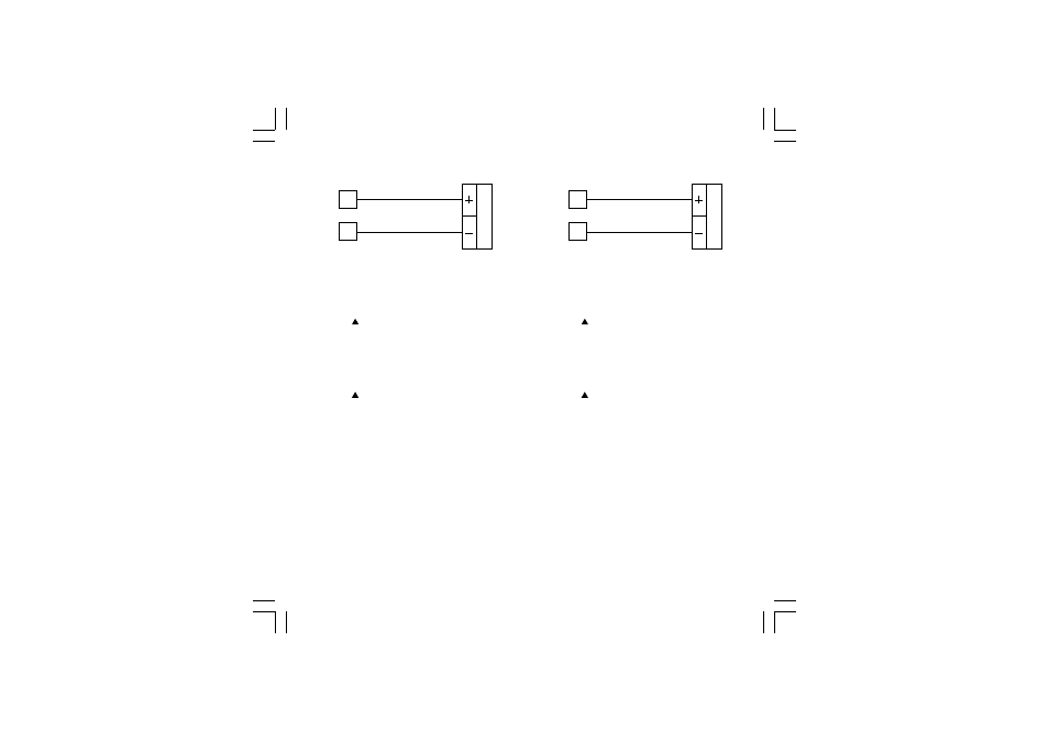
a) Connect calibrator and instrument as shown in
Figure 7.
10
9
Figure 7. Calibrator Connection
b) The upper display shows “OFF”, the lower displays
shows “AL”.
c) Set calibrator to 0.000 mA (even if the minimum range
value is 4mA).
d) Push the button; the display changes to “ON”.
e) After a few seconds, start calibration by pushing the
FUNC button. When this calibration is complete, the
instrument will go to the next parameter.
AH
Current Input Final Scale Value
a) Set the calibrator to 20 mA
b) Push the button; the displays will show “ON”
and “AH”.
c) After a few seconds, start calibration by pressing the
FUNC button. When this calibration is complete, the
instrument will go to the next parameter.
A.
Current Input Check
The display shows “A.” followed by a number showing the
measured value in counts.
a) Check the calibration (linear) by setting:
0.000 mA – the readout must be equal to
“A.000 00” ± 10 counts;
20.000 mA – the readout must be equal to
“A.300 00” ± 10 counts;
10.000 mA – the readout must be equal to
“A.150 00” ± 10 counts.
b) Push the FUNC button to go to the next parameter.
nL
5 VOLT Input Initial Scale Value
a) Connect calibrator and instrument as shown in
Figure 8.
10
9
Figure 8. Calibrator Connection
b) The upper display shows “OFF”, the lower displays
shows “nL”.
c) Set calibrator to 0.000 V (even if the minimum range
value is 1V).
d) Push the button; the display changes to “ON”.
e) After a few seconds, start calibration by pushing the
FUNC button. When this calibration is complete, the
instrument will go to the next parameter.
nH
5 Volt Input Final Scale Value
a) Set the calibrator to 5.000 V.
b) Push the button; the displays will show “ON”
and “nH”.
c) After a few seconds, start calibration by pressing the
FUNC button. When this calibration is complete, the
instrument will go to the next parameter.
n.
5 Volt Input Check
The display shows “n.” followed by a number showing the
measured value in counts.
a) Check the calibration by setting:
0.000 V – the readout must be equal to
“n.000 00” ± 10 counts;
5.000 V – the readout must be equal to
“n.300 00” ± 10 counts;
2.500 V – the readout must be equal to
“n.150 00” ± 10 counts.
b) Push the FUNC button to go to the next parameter.
7sl-6-00.p65
9/17/02, 2:44 PM
33